Broadband and wide wave beam microband antenna unit

A technology of microstrip antenna and wide bandwidth, which is applied in the direction of antenna, electrical components, radiation element structure, etc., can solve the problems of narrow beam and bandwidth, achieve mutual compensation and overcome the effect of narrow radiation beam

Inactive Publication Date: 2011-05-11
UNIV OF SCI & TECH OF CHINA
View PDF0 Cites 4 Cited by
  • Summary
  • Abstract
  • Description
  • Claims
  • Application Information

AI Technical Summary

Problems solved by technology

[0007] The present invention proposes a wide bandwidth beam microstrip antenna unit to overcome the defects of narrow beam and bandwidth existing in the existing microstrip antenna, and achieve the purpose of widening the beam and bandwidth

Method used


Image

  • Broadband and wide wave beam microband antenna unit
  • Broadband and wide wave beam microband antenna unit
  • Broadband and wide wave beam microband antenna unit

Examples


Embodiment 1

[0025] Embodiment 1: Wide Bandwidth Beam Microstrip Antenna Unit

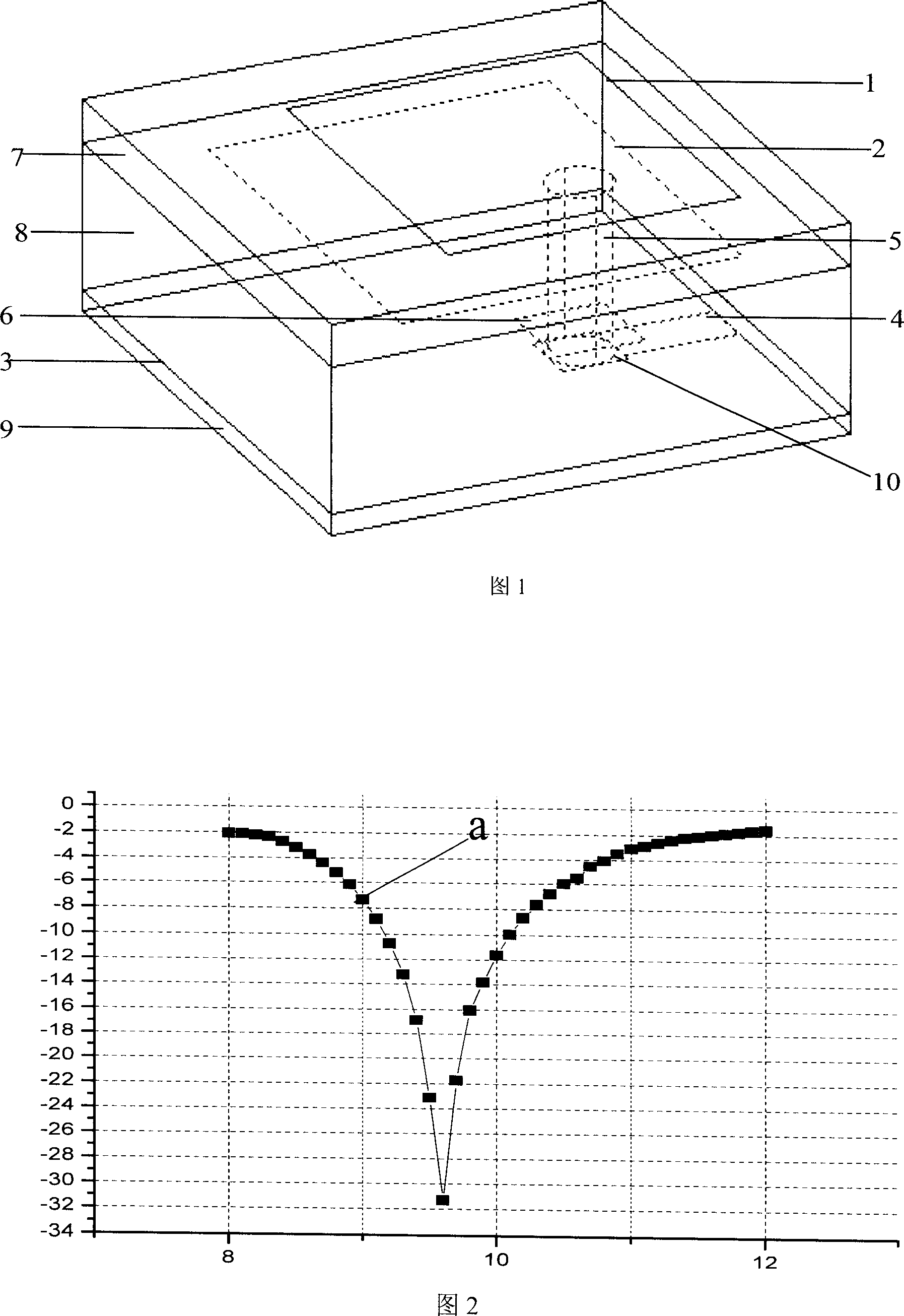
[0026] This embodiment adopts the combination of small hole coupling and multi-layer microstrip technology: three layers of rectangular metal patches with a dielectric constant of 1.07 to 2.2 and a thickness of 0.2mm and 2mm are sandwiched between four layers of rectangular metal patches whose length and width are respectively parallel to each other. The dielectric layer between them; the third layer of metal patch is the ground metal patch 3; the fourth layer of metal patch is used as the microstrip transmission line 4; the length of the long side of the second layer of metal patch 2 is longer than that of the first layer of metal patch The length of the long side of sheet 1 is not more than 1.4 times the length of the long side of the first metal patch 1, the length of the wide side of the second layer of metal patch 2 is longer than the wide side of the first layer of metal patch 1, and No more than 1.3 time...

Embodiment 2

[0045] Embodiment 2: L-band wide bandwidth beam microstrip antenna unit

[0046] This embodiment is composed of four layers of rectangular metal patches whose length and width are parallel to each other, and three dielectric layers with a dielectric constant of 1.07 to 2.2 and a thickness between 0.2mm and 2mm are sandwiched between them; the third layer of metal patch is grounded. Metal patch 3; the fourth layer of metal patch is used as a microstrip transmission line 4; the length of the long side of the second layer of metal patch 2 is longer than the long side of the first layer of metal patch 1, and does not exceed the length of the first layer of metal patch 1.4 times the length of the long side of sheet 1, the length of the wide side of the second layer of metal patch 2 is longer than that of the first layer of metal patch 1, and not more than 1.3 times the length of the wide side of the first layer of metal patch 1 ; Take the long side direction of each rectangular ent...

Embodiment 3

[0065] Example 3: Array Effects

[0066] Four identical antenna units in the above-mentioned embodiment 1 are fabricated together by printing technology, two horizontally and two vertically, forming a 2×2 array. In this array, the antenna units are symmetrical up and down, left and right antennas, the distance between the unit centers along the horizontal direction is 14mm, and the distance along the vertical direction is 13mm. Central location.

[0067] FIG. 5 shows a schematic diagram of the structure of the wide-bandwidth beam microstrip antenna unit in this embodiment after 2×2 array formation, wherein the horizontal axis is the x-axis, and the vertical axis is the y-axis. The input port is drawn from the microstrip transmission line labeled X in Figure 5, and each unit of the array is fed with equal amplitude and same phase.

[0068] In this embodiment, the following effects can be achieved after the wide bandwidth beam microstrip antenna unit is formed into a 2×2 array...


PUM


Abstract

A kind of broadband and broad-beam micro-strip antenna unit adopts keyhole coupling and multi-layer micro-strip technology and made up by four rectangular metal patches whose lengths and widths are parallel and three layers of medium layer. The third metal patch is grounding, and the fourth metal patch is micro-strip transmission line. Metal cylinder crosses a rectangular hole at the middle of metal patch without touching it, and its upper end connects with the second metal patch and its bottom end connects with micro-strip transmission line. Count to get the length and width of the first andsecond metal patch, the diameter of metal cylinder, length and width of rectangular hole, the thickness of each layer of medium, the length and width of micro-strip transmission line according to user's request. Adjust the place of metal cylinder crossing the rectangular hole according to the resonance frequency and matching instance. The frequency of micro-strip antenna unit is 3% to 10%, the unit standing wave of broadband VSWR is not bigger than 2.5, the width of unit wave arrives to 120 degree and gain undulation inside the taper space is less than 5dB.

Description

Technical field: [0001] The invention belongs to the technical field of microstrip antennas, in particular to a wide bandwidth beam microstrip antenna unit. Background technique: [0002] "Microstrip Antenna Design Handbook" (2001, pp269--275) published by Artech House, Boston London, USA introduces the characteristics and design methods of traditional microstrip antenna elements. Since the length of the traditional microstrip patch antenna is half the waveguide wavelength, which is a resonant structure, the main working mode of the traditional microstrip antenna is determined to be a single mode, that is, one of the main mode or the higher order mode, and the size of the antenna is relatively small. big. The working main mode of the traditional rectangular microstrip antenna is TM01 or TM10 mode, and the working main mode of the traditional circular microstrip antenna is TM11. They are all side-firing antennas, that is, the maximum radiation direction is perpendicular to t...

Claims


Application Information

Patent Timeline
Patent Type & Authority Patents(China)
IPC IPC(8): H01Q13/08H01Q1/38
Inventor 朱旗
Owner UNIV OF SCI & TECH OF CHINA
Why Eureka
Try Eureka