Direct electricity generation unit device of single tube double way liquid-state metal magnetic fluid wave energy

A power generation unit, liquid metal technology, applied in electromechanical devices, ocean energy power generation, electrical components, etc., can solve the problems of generator loss, large generator, and high cost, and achieve high power density, compact structure, and high conversion efficiency. Effect

Inactive Publication Date: 2007-06-27
INST OF ELECTRICAL ENG CHINESE ACAD OF SCI
View PDF3 Cites 13 Cited by
  • Summary
  • Abstract
  • Description
  • Claims
  • Application Information

AI Technical Summary

Problems solved by technology

However, in the process of operation, the generator of the AWS device showed obvious shortcomings: the generator is too large and the cost is too high; the suction between the mover and the stator is large, which brings great problems to the support syste

Method used


Image

  • Direct electricity generation unit device of single tube double way liquid-state metal magnetic fluid wave energy
  • Direct electricity generation unit device of single tube double way liquid-state metal magnetic fluid wave energy
  • Direct electricity generation unit device of single tube double way liquid-state metal magnetic fluid wave energy

Examples


Embodiment Construction

[0020] The present invention will be further described below in conjunction with specific embodiments and accompanying drawings.

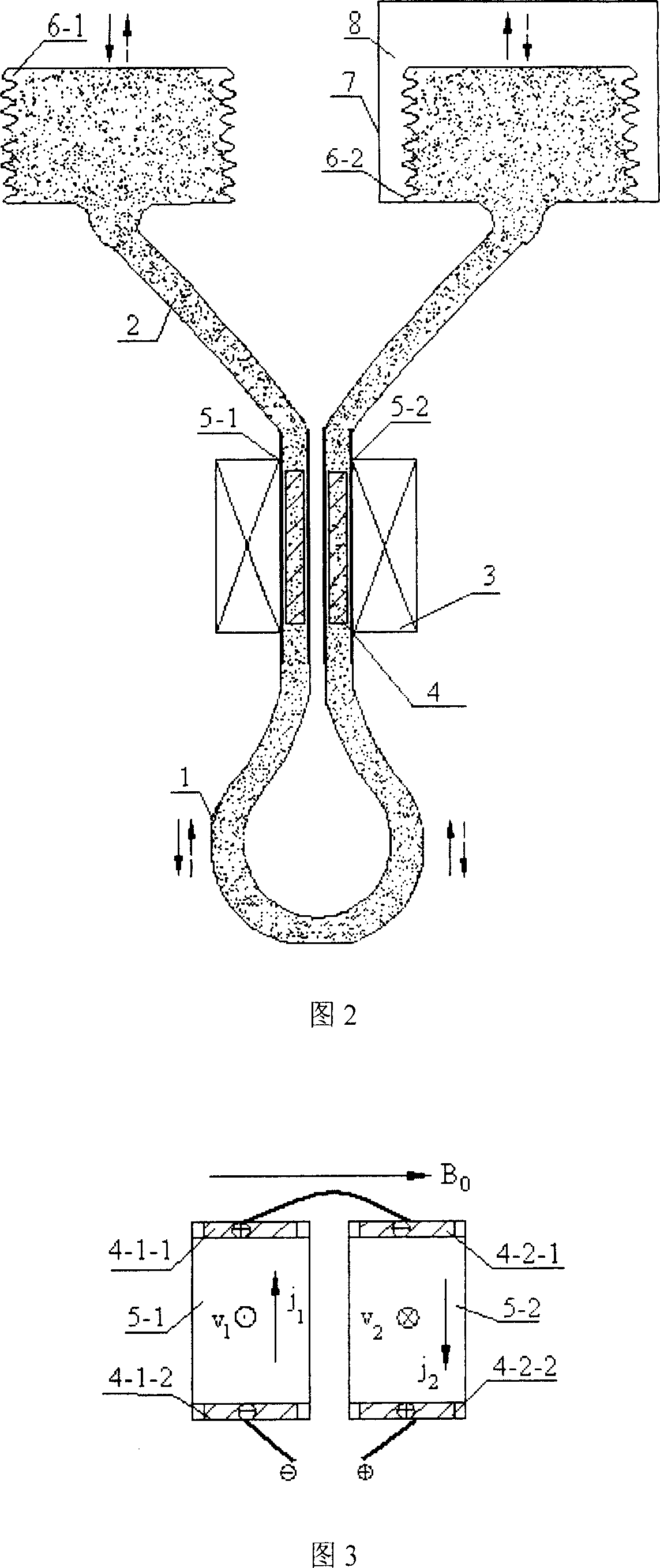
[0021] Fig. 2 is a schematic structural diagram of a specific embodiment of the present invention. As shown in Figure 2, the specific embodiment of the present invention consists of a U-shaped pipeline 1, a magnet 3, a magnetic fluid electrode 4, a left channel 5-1 for power generation, a right channel 5-2 for power generation, a left elastic container 6-1, and a right elastic container 6 -2, the rigid container 7 and the liquid metal 2 filled in the U-shaped pipe 1 and the elastic container 6-1, 6-2 are composed, and are vertically arranged in the seawater near the sea surface. The magnet 3 is a bipolar magnet; the U-shaped pipe 1 passes through the magnetic hole of the magnet 3 and forms a circular loop at its lower end; the U-shaped pipe is made of non-magnetic and non-conductive materials, and its cross-section is rectangular or square; the liq...


PUM


Abstract

An electric generation unit driven directly by wave energy in near sea and with dual channels formed by a single tube and liquid metal as magnetic fluid is composed of a magnetic body with central hole, magnetic fluid electrodes, a U-shaped tube passing through said central hole of magnetic body to form a lower annular loop, two elastic containers, and a rigid container. Under the action of wave energy, said liquid metal flows in U-shaped tube to generate inductive E.M.F. It has high output voltage.

Description

technical field [0001] The invention relates to a liquid metal magnetic fluid wave energy direct power generation device, in particular to a single-tube double-channel wave energy liquid metal magnetic fluid power generation unit device. technical background [0002] It has been the dream of mankind for hundreds of years to effectively utilize the huge ocean wave energy resources. With the aggravation of the greenhouse effect caused by the fossil energy crisis and environmental pollution, wave energy, as a clean and renewable energy, has increasingly attracted global attention, and wave energy power generation technology has developed rapidly. So far, there are about 10 wave power generation systems with an output power exceeding 100kW, and the maximum installed capacity has reached 750kW. [0003] At present, the wave energy generation system generally adopts the combination of oscillating water column and air impeller, oscillating float type, pendulum type, raft type and ...

Claims


Application Information

Patent Timeline
IPC IPC(8): F03B13/18H02K44/08
CPCY02E10/38Y02E10/30
Inventor 彭燕赵凌志沙次文李然许玉玉林佐伟
Owner INST OF ELECTRICAL ENG CHINESE ACAD OF SCI
Why Eureka
Try Eureka