
CAN bus data collector

A CAN bus, data acquisition technology, applied in the direction of bus network, circuit device, emergency protection circuit device, etc., can solve the problems of small driving ability, hidden safety hazards, and few AD conversion functions, and achieve the effect of strong driving ability

Inactive Publication Date: 2007-06-27
上海派恩科技有限公司
View PDF0 Cites 6 Cited by
  • Summary
  • Abstract
  • Description
  • Claims
  • Application Information

AI Technical Summary

Problems solved by technology

[0002] CAN bus data communication technology has been more and more widely used in various fields. Due to its structural reasons, the CAN bus data acquisition device of the prior art still has the following deficiencies: 1. It is only the input and output of the switching value, and there is an AD conversion Very few functions; 2. The output drive capacity is very small. If you want to drive a large load, you generally need to add a drive module; 3. Most of the communication methods use RS485, which is not suitable for high communication reliability requirements and communication data. 4. The compatibility of the product is low; 5. The modification of communication parameters is realized through the external DIP switch, which brings great potential safety hazards (if someone accidentally changes the position of the DIP switch, or someone Deliberately changing its position will cause communication failure and control failure); 6. The power module lacks complete protection measures, and some use methods that damage individual devices to protect other devices, such as adding TVS tubes to prevent exceeding the rated voltage, and some use fuses. Not only the size of the high-current fuse is relatively large and difficult to integrate into the circuit board, but also the response time of the fuse is quite slow, and it cannot effectively protect some devices that are sensitive to voltage requirements; 7. Lack of protection for the communication line CAN bus

Method used


Image

  • CAN bus data collector

Examples


Embodiment Construction

[0022] The present invention will be further described below in conjunction with the accompanying drawings and specific embodiments.

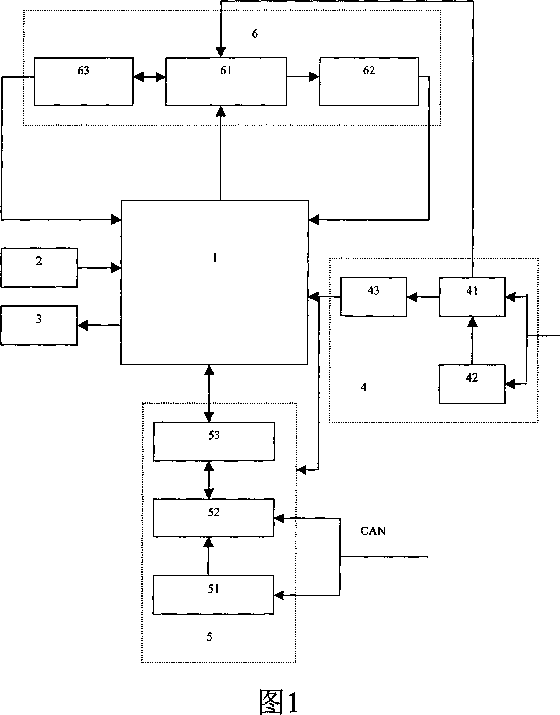
[0023] Referring to Fig. 1, CAN bus data acquisition device of the present invention comprises single-chip microcontroller unit 1, external switch signal input module 2 and switch signal output module 3 connected with single-chip microcontroller unit 1, also includes respectively and single A power detection and protection unit 4 , a CAN bus detection and protection unit 5 , and a closed-loop feedback network unit 6 connected to the chip microcontroller unit 1 . The power detection and protection unit 4 includes a power protection module 41, a power detection module 42 and a power conversion module 43. The input terminals of the power protection module 41 and the power detection module 42 are respectively connected to an external power supply, and the output terminals of the power detection module 42 are connected to the power protection module....


PUM


Abstract

This invention provides a CAN bus line data collecting device including a single-chip micro-controller unit, a supply detection and protection unit, a CAN bus detection and protection unit and a closed loop feedback network unit, in which, the supply detection and protection unit includes a protection module, a detection module and a conversion module, the CAN bus detection and protection unit includes a detection module, a protection module and a communication module for CAN bus, the closed loop feedback network unit includes a pulse width modulation signal drive module, a feedback module for pulse width modulation current and an increment coder interface module, which can prevent harm to the device from various abnormal input voltages and drive DC motors, magnetic valve and hydraulic pressure valve directly.

Description

technical field [0001] The invention relates to electrical equipment, in particular to a CAN bus data acquisition device. Background technique [0002] CAN bus data communication technology has been more and more widely used in various fields. Due to its structural reasons, the CAN bus data acquisition device of the prior art still has the following deficiencies: 1. It is only the input and output of the switching value, and there is an AD conversion Very few functions; 2. The output drive capacity is very small. If you want to drive a large load, you generally need to add a drive module; 3. Most of the communication methods use RS485, which is not suitable for high communication reliability requirements and communication data. 4. The compatibility of the product is low; 5. The modification of communication parameters is realized through the external DIP switch, which brings great potential safety hazards (if someone accidentally changes the position of the DIP switch, or so...

Claims


Application Information

Patent Timeline
Patent Type & Authority Applications(China)
IPC IPC(8): G08C19/00H04B3/50H04L12/40G05B15/02H02H3/00
Inventor 王智张卫东王峰马性辉
Owner 上海派恩科技有限公司
Learn More