
Method for manufacturing ic-embedded substrate

一种制造方法、内置基板的技术,应用在印刷电路制造、多层电路制造、半导体/固态器件制造等方向,能够解决成品率恶化、困难、无法露出衬垫电极等问题,达到防止数量增加、防止损伤的效果

Inactive Publication Date: 2007-06-27
TDK CORPARATION
View PDF3 Cites 5 Cited by
  • Summary
  • Abstract
  • Description
  • Claims
  • Application Information

AI Technical Summary

Problems solved by technology

First, since a load is applied to the substrate when polishing the entire surface of the embedded resin, there is a problem that the semiconductor IC chip may be damaged and the yield may deteriorate.
In addition, the condition setting range of the grinding amount is narrow, and it is very difficult to control the grinding variation to a minimum
Furthermore, when embedding a semiconductor IC chip with different heights of the pad electrodes, all the pad electrodes cannot be exposed.
In addition, when using semi-addition to carry out the electrical connection of the pad electrode and the wiring pattern, it is necessary to carry out no-field electroplating and electrolytic plating in sequence on the ground resin surface, but due to the gap between the ground resin surface and the no-electric field The bonding strength between them is low, so the deterioration of reliability occurs

Method used


Image

  • Method for manufacturing ic-embedded substrate
  • Method for manufacturing ic-embedded substrate
  • Method for manufacturing ic-embedded substrate

Examples


Embodiment Construction

[0033] Preferred embodiments of the present invention will be described in detail below with reference to the accompanying drawings.

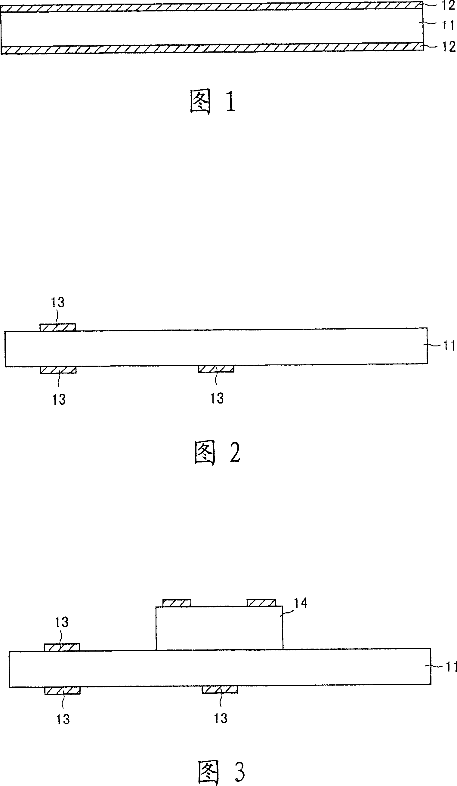
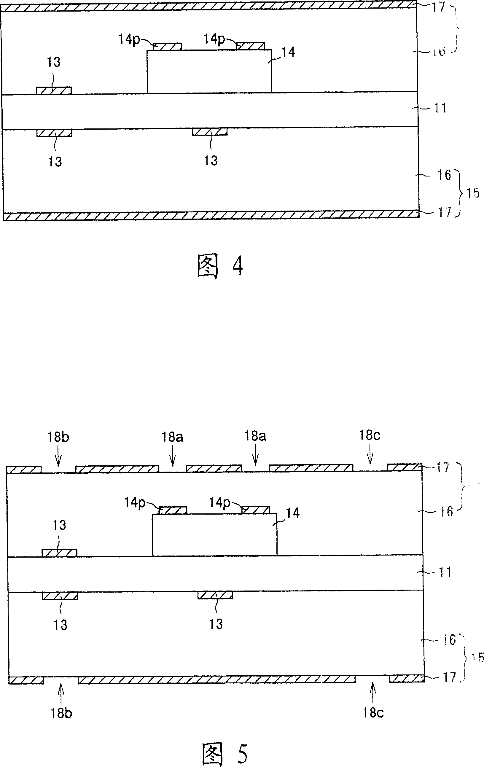
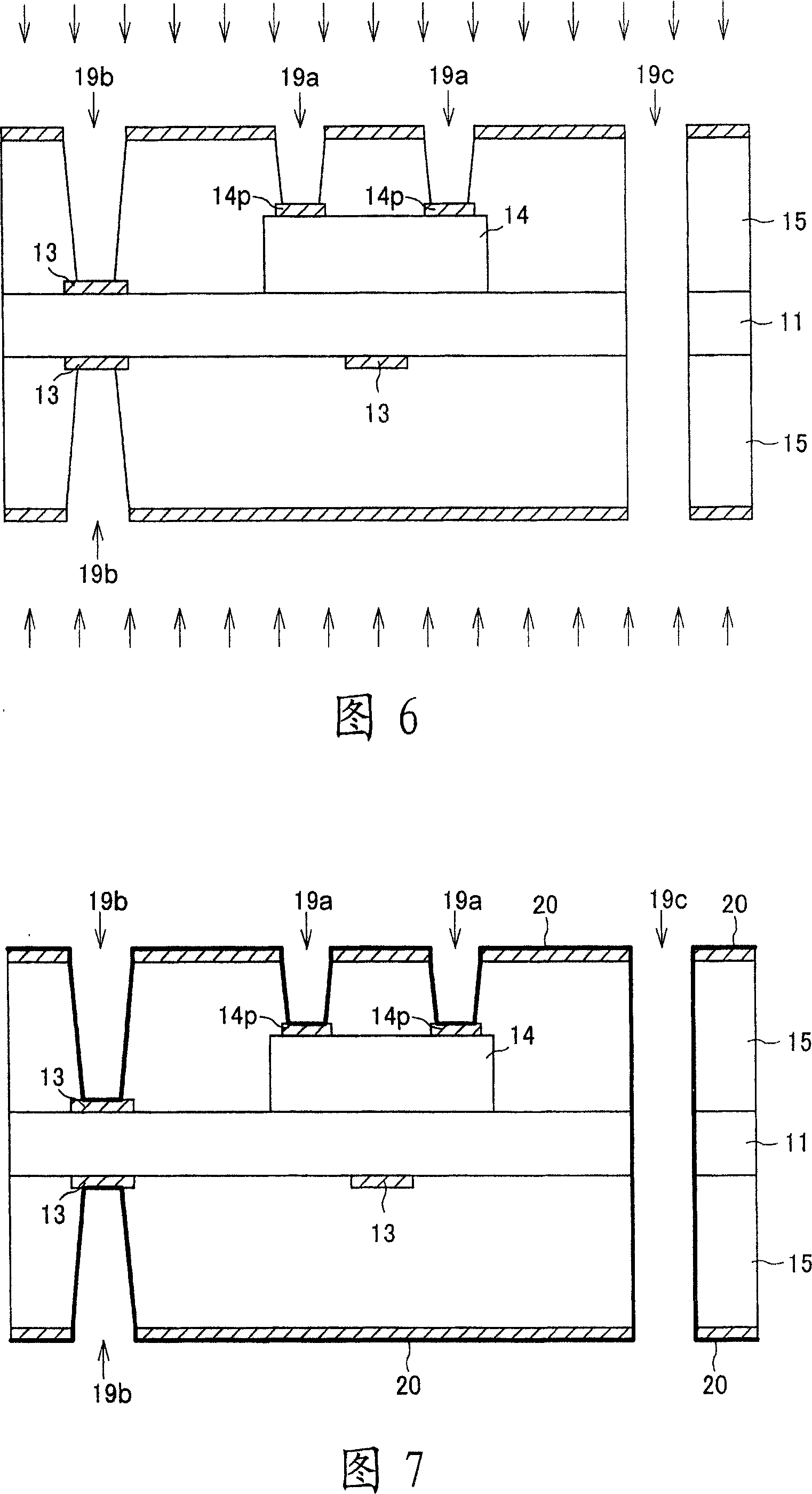
[0034] The method of manufacturing an IC-embedded substrate according to this embodiment can be applied to both the case of mounting a semiconductor IC chip on a "core substrate" constituting an IC-embedded substrate and the case of mounting a semiconductor IC chip on a "buildup layer" formed on a core substrate. Two situations. First, a first embodiment in which a semiconductor IC chip is mounted on a core substrate will be described in detail with reference to FIGS. 1 to 9 .

[0035]In the manufacture of the IC-embedded substrate of this embodiment, first, the core substrate 11 ( FIG. 1 ) is prepared. The core substrate 11 functions to secure the mechanical strength of the entire IC-embedded substrate and is not particularly limited, but for example, a resin substrate with copper foil on both sides can be used. As the material of the resin ...


PUM


Abstract

The invention provides a method for manufacturing an IC-embedded substrate without generating damages on a semiconductor IC chip embedded in a resin layer due to heating and weighting (stress), and is able to manage increase and finely spaced of number of pad electrodes. Firstly, a copper foil (12) disposed on either side of the core substrate (11) is selectively removed by photolithography and etching, whereby a conductor pattern (13) comprising wiring and lands is formed on the core substrate (11). Next, after a semiconductor IC chip (14) is mounted face up in a prescribed region on the core substrate (11), it is embedded in a resin sheet (16). Then, a copper foil (17) formed on a surface of the resin sheet (16) is selectively removed by shape-maintained machining, as as to form a mask pattern for forming an aperture. Thereafter, the aperture is formed by a sand-jetting processing in which the copper foil (17) applied with shape-maintained machining is used as the mask.

Description

technical field [0001] The present invention relates to a method for manufacturing an IC-embedded substrate, in particular to a method for forming a through-hole of a multilayer substrate with an IC embedded therein. Background technique [0002] Conventionally, as a high-density mounting structure of a printed wiring board, a structure in which a printed wiring board has a multilayer structure and a semiconductor IC chip is embedded therein is known (see Japanese Patent Application Laid-Open No. 2001-237347). In addition, as a method of exposing a pad electrode of a semiconductor IC chip built in a printed wiring board, for example, there is a method of forming a through hole directly above the pad electrode by laser processing (refer to Japanese Patent Application Laid-Open No. 9-321408 Publication) and the method of polishing the entire surface of the embedding resin layer of the semiconductor IC chip to expose the pad electrodes (refer to Japanese Patent Laid-Open No. 20...

Claims


Application Information

Patent Timeline
Patent Type & Authority Applications(China)
IPC IPC(8): H01L21/60H01L21/48H05K3/32H05K3/46
CPCH05K2201/09518H05K2203/025H05K3/4652H05K2201/09509H01L24/24Y10T29/49128H05K2201/0209H01L25/16Y10T29/49151H01L2924/01006H01L2924/01078H01L23/5389H01L2924/01043H01L2924/14H01L2224/73267H05K3/0044Y10T29/49139H01L2924/01005H01L2224/82039H01L2924/30107H01L24/82H05K2201/10674H05K2203/0554H05K1/185H01L2924/01029H01L2224/24226Y10T29/49155Y10T29/49126H01L2924/01033Y10T29/4913H01L21/3205
Inventor 长瀬健司川畑贤一
Owner TDK CORPARATION
Learn More