Buried tube type bubbling bed direct carbon fuel cell

A fuel cell and bubbling bed technology, applied in the field of direct carbon fuel cell devices, can solve unfavorable carbon and anode direct contact mechanism reaction, anode surface solid carbon fuel feeding problem, unfavorable carbon and anode non-contact mechanism reaction, etc. problems, to achieve the effect of easy sealing, convenient current collection, and less carrier gas

Active Publication Date: 2007-06-27
TSINGHUA UNIV
View PDF0 Cites 12 Cited by
  • Summary
  • Abstract
  • Description
  • Claims
  • Application Information

AI Technical Summary

Problems solved by technology

[0005] At present, the international solid oxide electrolyte direct carbon fuel cell research mostly stays in the single-cell experiment stage, and the practical application still faces the problem of feeding solid carbon fuel on the anode surface, especially when the anode surface is in direct contact with the anode surface after a period of reaction. The problem of continuous feeding when the solid carbon fuel has been completely reacted
At the same time, the direct carbon fuel cell with fixed bed structure is not conducive to the occurrence of non-contact mechanism reaction between carbon and anode, and is also not conducive to internal heat and mass transfer. The circulating fluidized bed direct carbon fuel cell proposed by Stanford University in the United States can solve the problem to a certain extent. It is also conducive to the occurrence of non-contact mechanism reaction between carbon and anode, but this design is not conducive to the occurrence of direct contact mechanism reaction between carbon and anode. At the same time, the structure is complex and the battery wears a lot

Method used


Image

  • Buried tube type bubbling bed direct carbon fuel cell
  • Buried tube type bubbling bed direct carbon fuel cell
  • Buried tube type bubbling bed direct carbon fuel cell

Examples


Embodiment 1

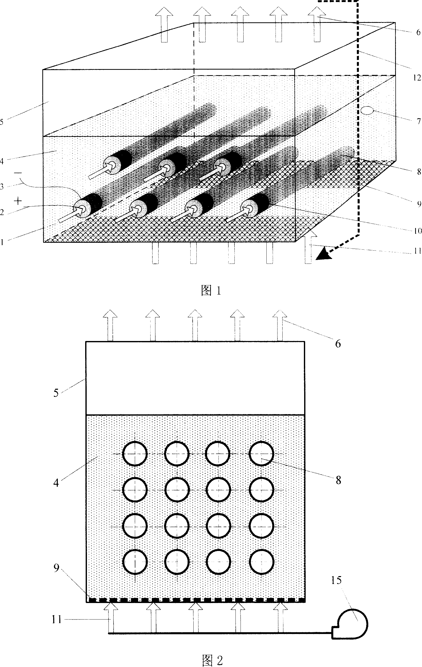
[0032] A buried tube type bubbling bed direct carbon fuel cell, which includes a bubbling bed 5, 16 dead-tube solid oxide fuel cell cells 8 with an anode on the outside and a cathode on the inside, and an air distribution plate 9 with a diameter of 5mm ~50μm powdered solid carbon fuel—graphite 4 and air supply device 15;

[0033] As shown in Fig. 2, Fig. 2 is a schematic diagram of the structure of the parallel buried tube type bubbling bed in Embodiment 1. The air distribution plate 9 is installed at the bottom of the bubbling bed 5, and 16 dead-pipe solid oxide fuel cell cells 8 are inserted into the bubbling bed 5 along the horizontal direction, and the open ends of the dead-pipe solid oxide fuel cell cells 8 are located in the bubbling bed. Outside the bubble bed 5, the closed end is located inside the bubble bed 5, and the joint between the bubble bed 5 and the solid oxide fuel cell unit 8 is sealed with high-temperature ceramic glue 10, and the interface structure is sho...

Embodiment 2

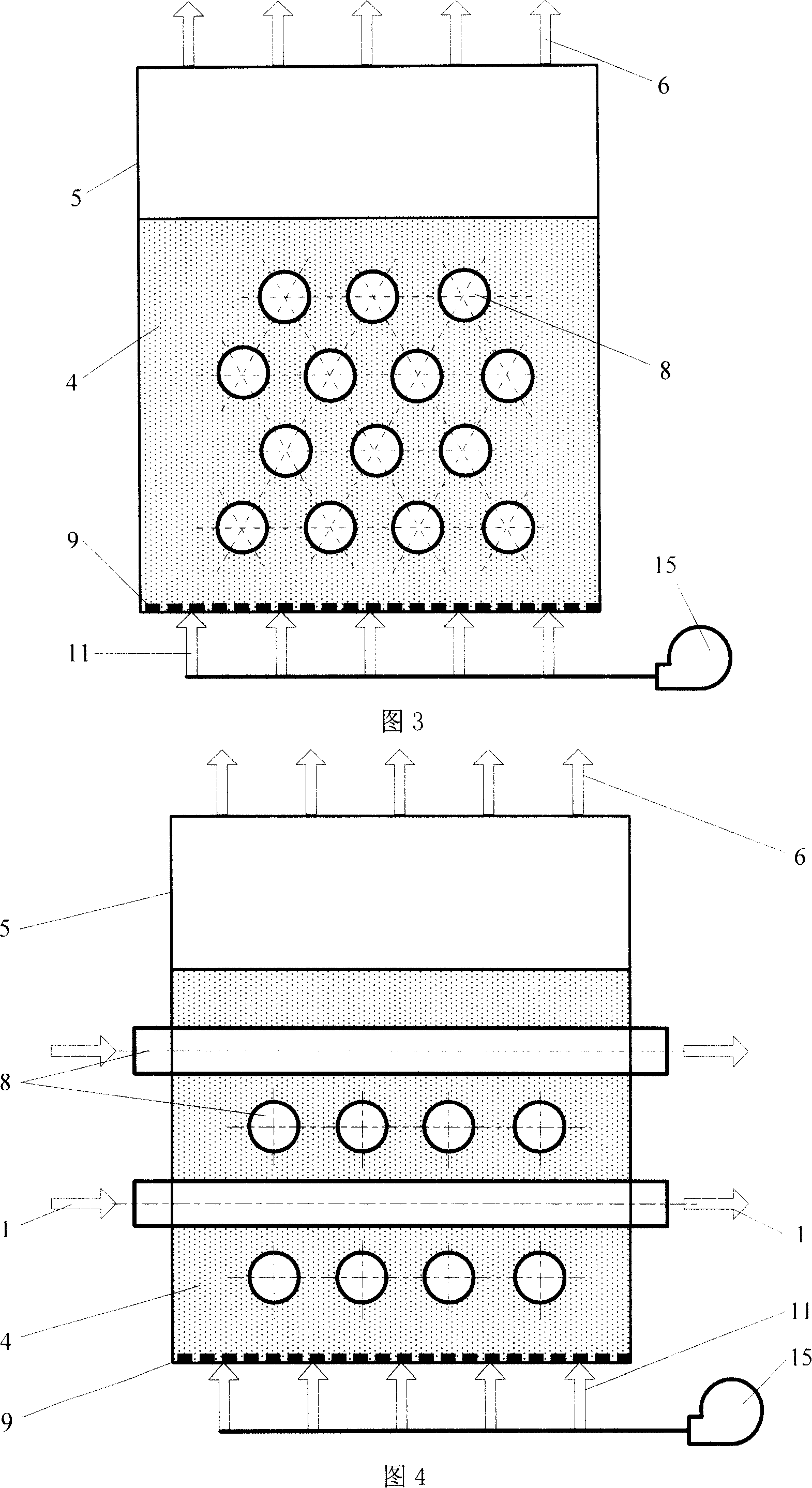
[0037] A buried tube type bubbling bed direct carbon fuel cell, which includes: bubbling bed 5, 14 blind tube solid oxide fuel cell cells 8 with anodes on the outside and cathodes on the inside, and an air distribution plate 9 with a diameter of 5mm-50μm powdered solid carbon fuel—coke 4 and air supply device 15.

[0038] As shown in Fig. 3, Fig. 3 is a schematic diagram of the structure of the fork row buried tube type bubbling bed in Embodiment 2. Install the air distribution plate 9 on the bottom of the bubbling bed 5, insert 14 dead-pipe solid oxide fuel cell cells 8 into the bubbling bed 5 along the horizontal direction, and open the open ends of the dead-pipe solid oxide fuel cell cells 8 Located outside the bubbling bed 5, the closed end is located inside the bubbling bed 5, and the joint between the bubbling bed 5 and the solid oxide fuel cell unit 8 is sealed with high-temperature ceramic glue 10, and the interface structure is shown in Figure 8. Embodiment 2 Solid o...

Embodiment 3

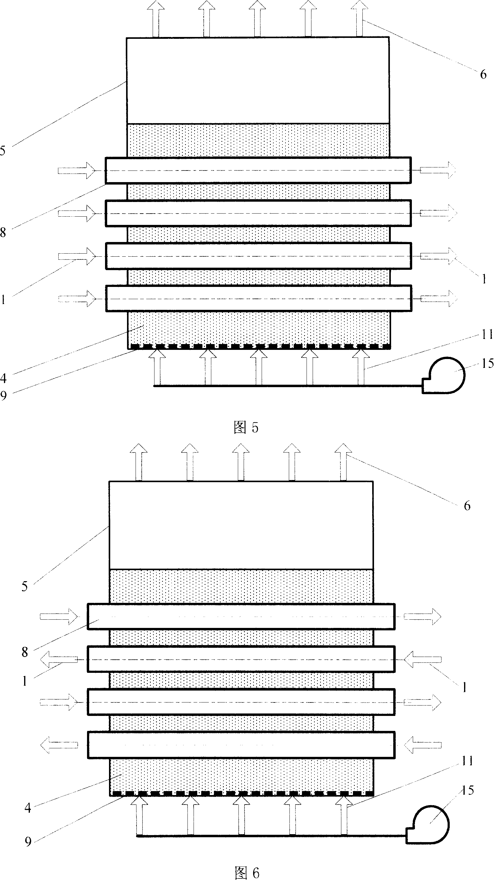
[0042] A buried tube type bubbling bed direct carbon fuel cell, which includes: bubbling bed 5, 16 through-tube solid oxide fuel cell cells 8 with an anode on the outside and a cathode on the inside, and an air distribution plate 9 with a diameter of 5mm-50μm powdered solid carbon fuel——carbon black 4 and air blower 15 .

[0043] As shown in Figure 4, the air distribution plate 9 is installed at the bottom of the bubbling bed 5, and 16 through-tube solid oxide fuel cell cells 8 are inserted into the bubbling bed 5 along the horizontal direction, and the through-tube solid oxide fuel cell The open ends on both sides of the battery cell 8 are located outside the bubbling bed 5, and the joint between the bubbling bed 5 and the solid oxide fuel cell 8 is sealed with high-temperature ceramic glue 10. The interface structure on both sides of the tube is shown in Figure 9 Show. Embodiment 3 Solid oxide fuel cell cells 8 are arranged layer by layer in a staggered arrangement. The po...


PUM


Abstract

This invention relates to a buried bubble bed direct carbon fuel cell including a bubble bed, tube solid oxide fuel cell monomers, an air distribution board and solid carbon fuel and wind feed device, in which, the monomers are arranged crossly, in sequence or in stagger to be plugged in the buble bed horizontally, the joint places of the monomers and the bed are sealed, the tube solid oxide electrolyte fuel battery is buried in the solid fuel to form a tube-buried structure, the wind feeding device sends gas into the bed via the distributing board to blow up solid carbon fuel particles, and the working temperature of the bed is 700-1000deg.C, the inside tube of the cell is output positive and the outside is output negative and the reacted anode gas is discharged from the top of the bed .

Description

technical field [0001] The invention relates to a buried tube type bubbling bed direct carbon fuel cell, which belongs to the technical field of direct carbon fuel cell devices. Background technique [0002] At present, fuel cell technology has become one of the research hotspots at home and abroad because of its remarkable advantages. Direct Carbon Fuel Cell (DirectCarbon Fuel Cell, DCFC) is also a kind of fuel cell. Unlike batteries that use gas or liquid fuel, DCFC uses solid carbon as fuel. Its unique advantages are: the theoretical efficiency of the battery is higher; the use of solid carbon fuel , save the gasification link, and at the same time, the solid carbon fuel has small volume, high calorific value, convenient transportation and storage, is not easy to leak and explode, and reduces the requirements for battery sealing, especially high-temperature sealing; Coal is obtained through simple processing, and the fuel is easier and more widely obtained than hydrogen ...

Claims


Application Information

Patent Timeline
Patent Type & Authority Applications(China)
IPC IPC(8): H01M8/00H01M8/10H01M8/04H01M8/06H01M8/1009
CPCY02E60/521Y02E60/50
Inventor 蔡宁生李晨史翊翔
Owner TSINGHUA UNIV
Why Eureka
Try Eureka