Wireless radio frequency transceiver system for internet of things

Active Publication Date: 2018-06-19
NAT CHENG KUNG UNIV
View PDF7 Cites 15 Cited by
  • Summary
  • Abstract
  • Description
  • Claims
  • Application Information

AI Technical Summary

Benefits of technology

[0018]Compared to the conventional technology, the wireless radio frequency transceiver system of the invention has a wireless radio frequency receiving module that utilizes a harmonic detection technique to perform demodulation. This can significant simplify complexity of the wireless radio frequency receiving module, reduce system power consumption and area, and thereby fac

Problems solved by technology

Taking the wireless RFID system used in IOT as an example, an analog integrated circuit, a digital integrated circuit and a wireless radio frequency integrated circuit are often integrated in the same System on Chip (SOC) in response to continuing development of the integrated circuits, wherein the wireless radio frequency integrated circuit however usually takes up the entire system power consumption.
This dramatically increases power consumption of the wireless radio frequency transceiver system and shortens its use time.
Moreover, the transmitter part of the wireless radio frequency transceiver system usually has higher p

Method used


Image

  • Wireless radio frequency transceiver system for internet of things
  • Wireless radio frequency transceiver system for internet of things
  • Wireless radio frequency transceiver system for internet of things

Examples


Embodiment Construction

[0028]Embodiments of the present invention will now be described in detail with reference to the accompanying drawings. The invention may, however, be embodied in many different forms and should not be construed as being limited to the embodiments set forth herein. Rather, these embodiments are provided so that this disclosure will be thorough and complete, and will fully convey the scope of the invention to those skilled in the art. In the drawings, the shapes and dimensions of elements may be exaggerated for clarity, and the same reference numerals will be used throughout to designate the same or like components.

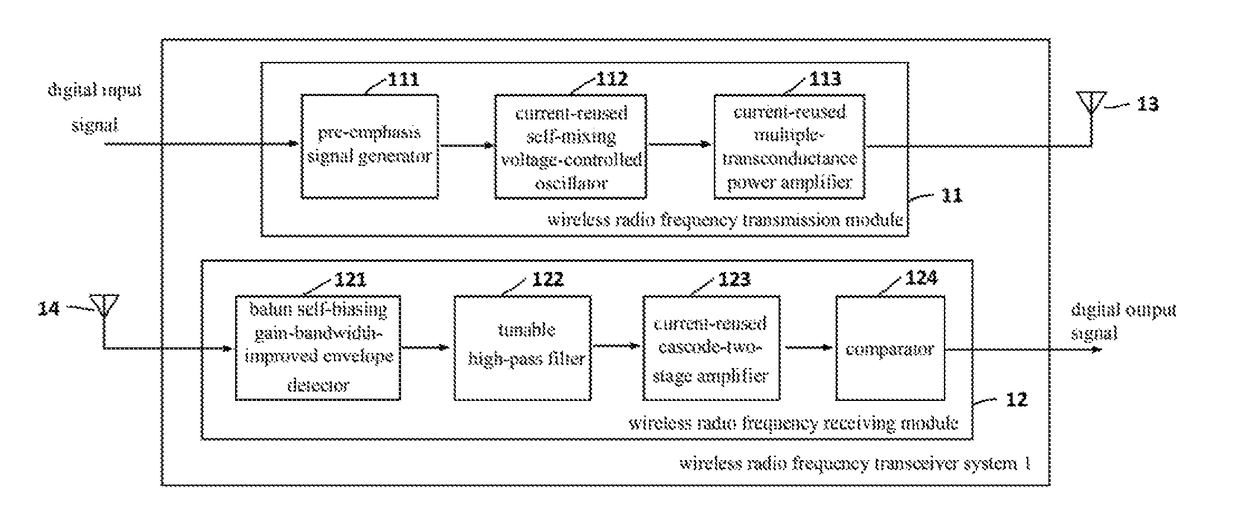
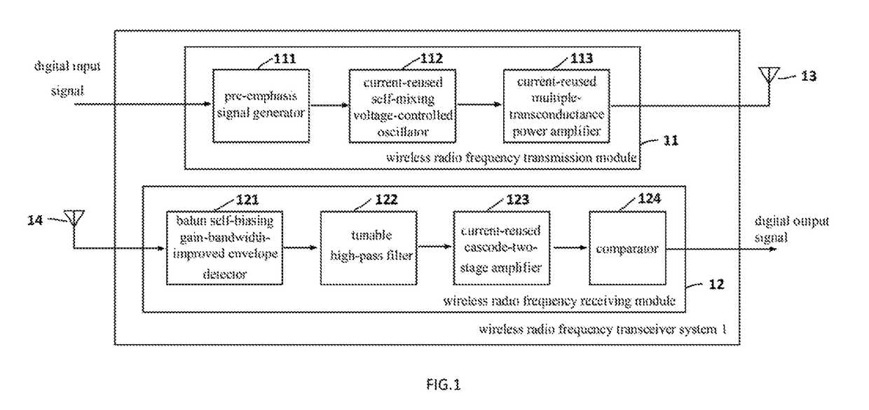
[0029]Refer to FIG. 1, which is a system architecture diagram of a wireless radio frequency transceiver system of the invention. Generally, the wireless radio frequency transceiver system 1 of the invention is applicable to Internet of Things (TOT) and utilizes a harmonic detection technique to simplify its system circuit design, thereby reducing power consumption and area...


PUM


Abstract

A wireless radio frequency transceiver system for Internet of Things includes: a wireless radio frequency transmission module and a wireless radio frequency receiving module. The wireless radio frequency transmission module is used to shape signal waveform of digital signals from the Internet of Things to modulate the digital signals to form modulated output signals, and adopt a self-mixing technique to increase voltage/current amplitude of the modulated output signals and reduce phase noise. The wireless radio frequency transmission module is further used to adopt a current reuse technique to amplify the voltage/current amplitude of the modulated output signals, and transmit the amplified modulated output signals through a first antenna to a wireless channel. The wireless radio frequency receiving module is used to detect carrier input signals received from a second antenna to obtain baseband signals and demodulate the baseband signals to form differential signals. The wireless radio frequency receiving module is further used to amplify voltage/current amplitude of the demodulated differential signals several times in an open loop state to produce digital output signals, and transmit the digital output signals to a back-end signal processor.

Description

CROSS-REFERENCE TO RELATED APPLICATIONS[0001]This application claims the priority of Republic of China Patent Application No. 106128190 filed on Aug. 18, 2017, in the State Intellectual Property Office of the R.O.C., the disclosure of which is incorporated herein by reference.BACKGROUND OF THE INVENTIONField of the Invention[0002]The invention relates to wireless radio frequency transceiver technologies, and more particularly, to a wireless radio frequency transceiver system applicable to Internet of Things and having low power consumption.Descriptions of the Related Art[0003]Communication technologies through computers, Internet and so on have boomed, and then Internet of Things (JOT) has become popular recently in terms of its capability of connecting all objects to the Internet by means of signal transmitting or sensing equipment to achieve object recognition and intelligent management, wherein the signal transmitting or sensing equipment is, for example, wireless Radio Frequency...

Claims


Application Information

Patent Timeline
IPC IPC(8): H04B1/40H03F3/24H04B1/16H03F1/22H03F3/19H03F3/62H03B5/12
CPCH04B1/40H04B1/16H03F3/245H03F1/223H03B5/1212H03F3/62H03F3/19H03F2200/102H03F2200/06H03F2200/168H03F2200/555H03F2200/451H03F2200/411H03B5/1215H03B5/1228H03B5/1243H03B2200/009H03F3/45188
Inventor LEE, SHUENN-YUHTSOU, CHING-FU
Owner NAT CHENG KUNG UNIV
Why Eureka
Try Eureka