Film ozonolysis in a tubular or multitubular reactor

a technology of film ozonolysis and tubular or multi-tubular reactor, which is applied in the direction of carbonyl compound preparation, liquid-gas reaction of thin-film type, water/sewage treatment by oxidation, etc., can solve the problems of significant explosion risk, peroxide intermediate, and technology that has not been adapted for large-scale (multi-ton) manufacturing processes, etc., to facilitate gaseous reagent diffusion, reduce mechanical energy, and simplify reaction setup

Active Publication Date: 2018-09-11
P2 SCI INC
View PDF8 Cites 10 Cited by
  • Summary
  • Abstract
  • Description
  • Claims
  • Application Information

AI Technical Summary

Benefits of technology

[0004]The approach to ozonolysis described herein functions using gravity assisted co-current reagent flow to facilitate gaseous reagent diffusion into a liquid or emulsified reagent, which simplifies the reaction setup and minimizes the mechanical energy required, all while achieving a scalable and continuous process that does not allow for the accumulation of large amounts of hazardous intermediates, thus rendering the process and equipment described herein suitable for large, industrial-scale ozonolysis.
[0006](a) homogeneity of the reagent-containing film and thermal exchange is maximized,
[0007](b) selection of the optimum size of the individual tubes is based on the best compromise between maximum internal diameter (for optimum throughput) and minimum height (for reduced head loss) while maintaining mechanical simplicity (for reduced maintenance), and

Problems solved by technology

The use of either type of established method, however, results in the accumulation of peroxide intermediates that can be unstable and present a significant explosion risk.
These technologies, however, have not been adapted for use in large-scale (multi-ton) manufacturing processes, owing to challenges with throughput and the operation costs associated with maintaining large numbers of reaction vessel channels and precisely calibrated instruments.

Method used


Image

  • Film ozonolysis in a tubular or multitubular reactor

Examples


example 1

Film Ozonolysis in a Monotubular Reactor

Ozonolysis Reactor Details

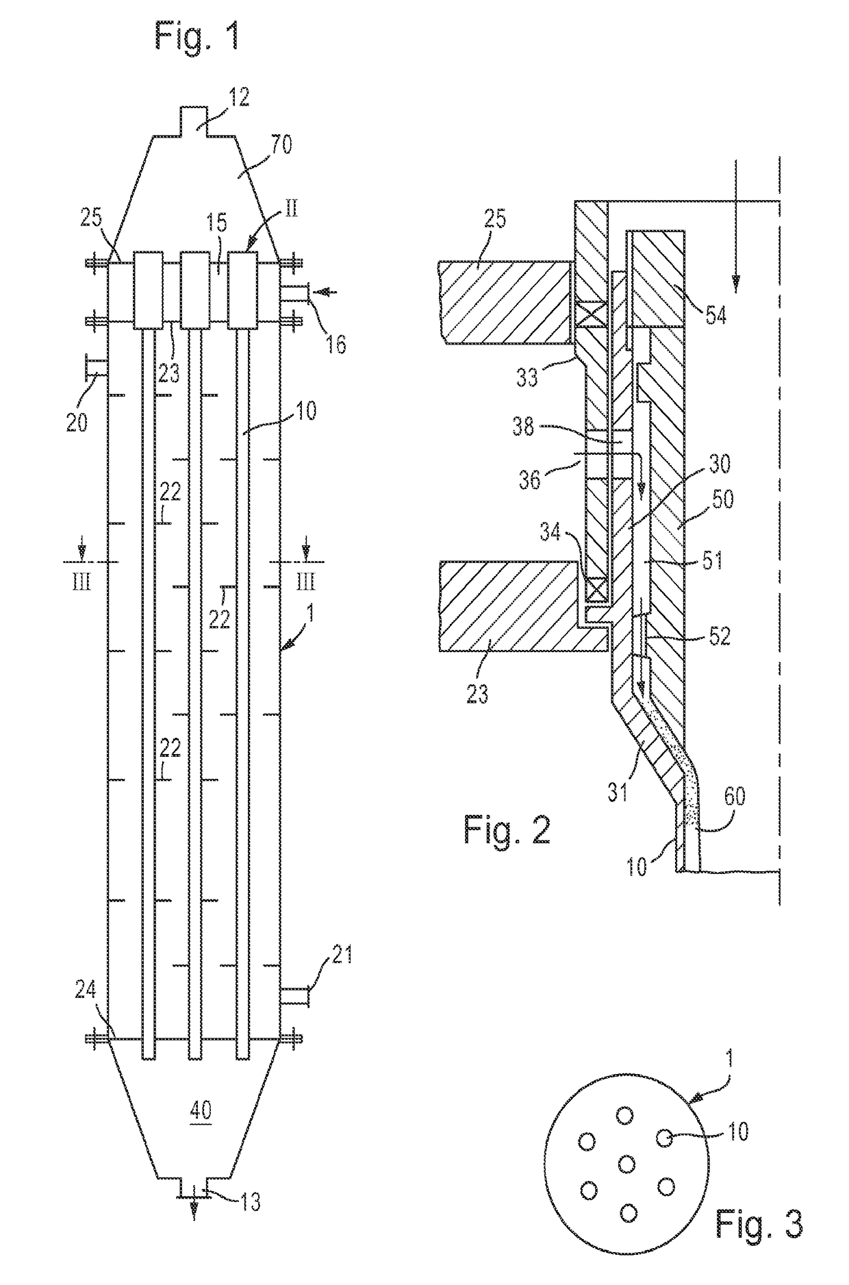
[0115]A pilot tube reactor was used for ozonolysis, including a tube with a 10 mm internal diameter and a length of 1.7 m (e.g., 10 in FIG. 1). The tube was constructed of 316 stainless steel and was connected to a gaseous reagent feeding chamber (e.g., 70 in FIG. 1) that allowed gas to be flowed through the center of the tube and liquid to be flowed in a film on the wall of the tube through annular slots (e.g., as shown in FIG. 2; component II in FIG. 1). The tube was enclosed in a steel jacket (e.g., 1 in FIG. 1) for circulating cooling fluid around the reaction tube (e.g., 10 in FIG. 1) with the end of the tube protruding through a liquid-sealed orifice (e.g., 24 in FIG. 1). A liquid / gas separation vessel was connected to the bottom of the reaction tube (e.g., 10 in FIG. 1). The excess gas flowed through to an ice condenser followed by an ozone destruction unit. The collected liquid product was pumped through a per...

example 2

Ozonolysis Reactor 2 Details

[0125]A second arrangement of involving 3 pilot tube reactors connected in series was used. All 3 tubes were 1.7 m in length, with the first 2 tubes being 25 mm in diameter and the 3rd tube being 10 mm in diameter. All tubes were equipped with a film distribution head, a cooling jacket, and a gas liquid separator at the bottom. The organic, liquid feed was flowed from the first tube through the second and third tube in series. The gas was flowed co-currently from the 3rd tube through the 2nd to the 1st tube. The cooling jacket temperature was maintained at 15° C.

[0126]In one instance, this reactor was used to process a 75% mixture of vegetable fatty acid in nonanoic acid. The major components of the vegetable fatty acid were estimated as follows: 77.65% oleic acid, 11.64% linoleic acid, 1.98% stearic acid, 4.4% palmitic acid, 2.9% myristic acid. The O3 was generated using pure O2 and a generator composed of 2 Pinnacle Quadblocks in a custom cabinet. The r...


PUM

PropertyMeasurementUnit
gas flow rateaaaaaaaaaa
diameteraaaaaaaaaa
diameteraaaaaaaaaa

Abstract

The disclosure relates to a method of performing ozonolysis or ozone-based oxidation on a liquid or emulsified reagent using a tubular falling film reactor with one or multiple tubes wherein the combined ozone and carrier gas flow is co-current.

Description

CROSS-REFERENCE TO RELATED APPLICATIONS[0001]This application is a U.S. National Phase application, filed under 35 U.S.C. 371(c), of International Application No. PCT / US2015 / 036589, filed Jun. 19, 2015, which claims the benefit of and priority to U.S. Provisional Application No. 62 / 015,311, filed Jun. 20, 2014, and U.S. Provisional Application No. 62 / 163,022, filed May 18, 2015, each of which is incorporated herein by reference in its entirety.BACKGROUND[0002]Ozonolysis or ozone-based oxidation of reagents currently in use in the chemical industry generally rely on processing large amounts of material in either tray-type continuous ozonation systems or in batch systems, e.g., U.S. Pat. No. 2,813,113. The use of either type of established method, however, results in the accumulation of peroxide intermediates that can be unstable and present a significant explosion risk. Alternatively, processing small amounts of material in a continuous fashion can significantly reduce these risks. S...

Claims


Application Information

Patent Timeline
Patent Type & Authority Patents(United States)
IPC IPC(8): C07C45/00C07C45/40C02F1/78B01J19/24B01J10/02B01J19/00B01J10/00C02F101/30
CPCC07C45/40B01J10/02B01J19/247B01J19/2415C02F1/78B01J19/2425C07C2601/16B01J2219/24C02F2101/30C02F2201/784C07C51/34C07C47/42C07C47/19C07C53/126
Inventor FOLEY, PATRICKBURNS, NEILCHAPEAUX, ALEXANDREADAMI, ICILIOMILICIA, ANTONIO
Owner P2 SCI INC
Why Eureka
Try Eureka