Electric power supply system for vehicle

a technology for electric power supply and vehicle, which is applied in the direction of battery/fuel cell control arrangement, exchanging data chargers, transportation and packaging, etc., can solve the problems of high reproducibility, inability to obtain the voltage fluctuation width required, and inability to obtain high-accuracy calculation results, etc., to achieve greater voltage fluctuation width of the second battery, reduce the variation of the calculation result, and reduce the effect of internal resistan

Active Publication Date: 2018-11-20
TOYOTA JIDOSHA KK
View PDF15 Cites 2 Cited by
  • Summary
  • Abstract
  • Description
  • Claims
  • Application Information

AI Technical Summary

Benefits of technology

[0009]Accordingly, the disclosure provides an electric power supply system for a vehicle in which a first battery and a second battery are connected in parallel, having an advantage of calculating internal resistance of the second battery with high reproducibility and high accuracy.
[0011]With this, the voltage of the alternator or the direct current to direct current converter fluctuates according to the predetermined voltage waveform, and it is possible to make voltage fluctuation in the second battery when calculating internal resistance more uniform than voltage fluctuation with operation of the electric load. Then, since it is possible to calculate the internal resistance of the second battery using the voltage value and the current value detected in a state where voltage fluctuation in the second battery is made uniform, it is possible to suppress variation in a calculation result compared to a case of calculating internal resistance using voltage fluctuation with operation of the electric load. That is, it is possible to realize high reproducibility in calculation of internal resistance.
[0012]In addition, since it is possible to make the voltage of the alternator or the direct current to direct current converter fluctuate according to the predetermined voltage waveform, it is possible to make the voltage fluctuation width of the second battery greater than voltage fluctuation with operation of the electric load. Then, since it is possible to calculate the internal resistance of the second battery using the voltage value and the current value detected in a state where the voltage fluctuation width of the second battery is made greater, it is possible to improve calculation accuracy compared to a case of calculating internal resistance using voltage fluctuation with operation of the electric load. That is, it is possible to realize high accuracy in calculation of internal resistance.
[0013]According to the above-described aspect, in the electric power supply system for a vehicle in which the first battery and the second battery are connected in parallel, it is possible to calculate the internal resistance of the second battery with high reproducibility and high accuracy.
[0015]In the above-described aspect, the predetermined voltage waveform may be generated based on an upper limit voltage value for preventing the first battery from being overcharged and a lower limit voltage value for suppressing a decrease in charging rate of the first battery.

Problems solved by technology

As a result, even if the internal resistance of the second battery is calculated by the above-described method, high reproducibility is not obtained.
As a result, it is not possible to obtain a voltage fluctuation width required for calculating the internal resistance with satisfactory accuracy, and even if the internal resistance of the second battery is calculated by the above-described method, a high-accuracy calculation result is not obtained.

Method used


Image

  • Electric power supply system for vehicle
  • Electric power supply system for vehicle
  • Electric power supply system for vehicle

Examples


third embodiment

[0119]In contrast, in a third embodiment, a case where a control target for realizing voltage fluctuation and current fluctuation of the second battery is connected in series with the second battery 160 will be described.

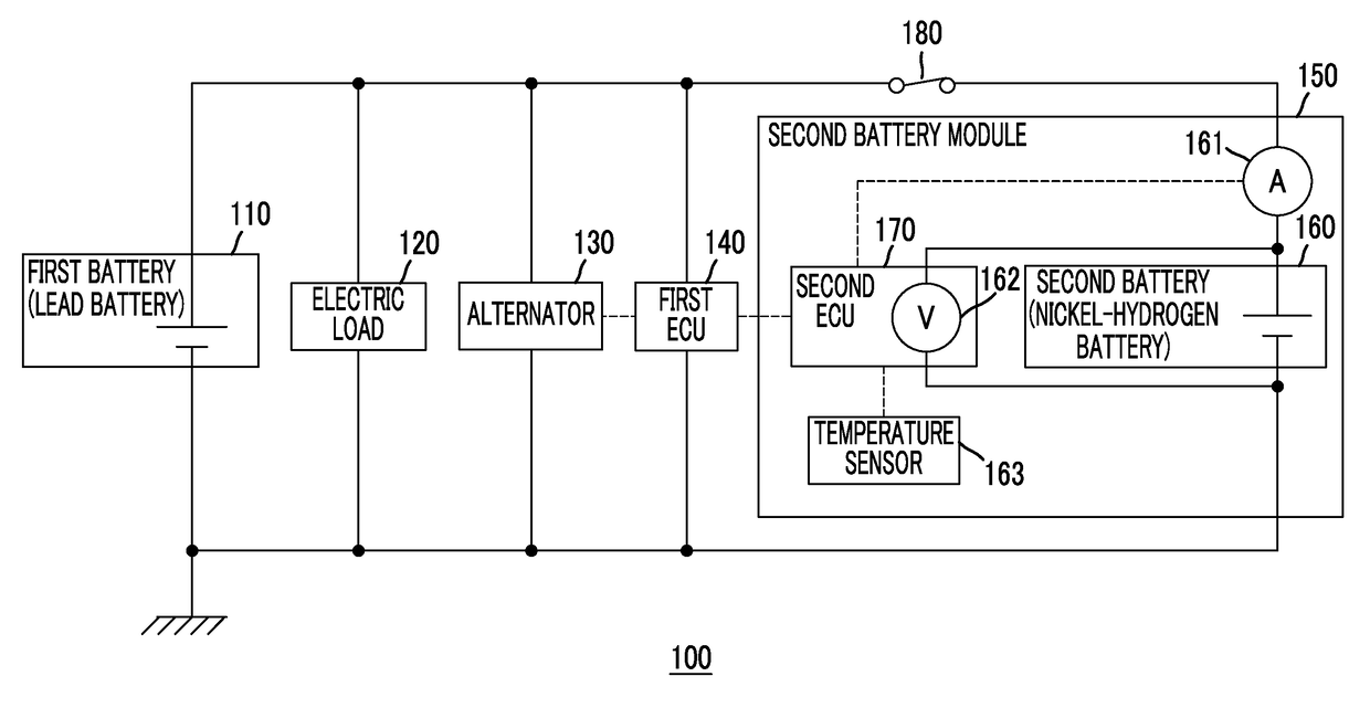
[0120]FIG. 9 is a diagram showing another configuration example of an electric power supply system for a vehicle. An electric power supply system 900 for a vehicle shown in FIG. 9 is an electric power supply system for a vehicle which supplies electric power to an electric load mounted in a vehicle, and is an electric power supply system which is applied to, for example, a hybrid vehicle or the like.

[0121]As shown in FIG. 9, in a case of the electric power supply system 900 for a vehicle, a DC / DC converter 910 which is a control target for realizing voltage fluctuation and current fluctuation of the second battery is connected in series with the second battery 160.

first embodiment

[0122]In the electric power supply system 900 for a vehicle shown in FIG. 9, it is assumed that a second ECU 920 has a function of the first ECU 140, in addition to the function of the second ECU 170 described in the

[0123]The second ECU 920 makes an output voltage of the DC / DC converter 910 fluctuate according to a predetermined voltage waveform. With this, according to the electric power supply system 900 for a vehicle, it is possible to calculate the internal resistance of the second battery 160 with high reproducibility and high accuracy.

[0124]In the first to third embodiments, in generating the voltage waveform based on the upper limit voltage value, the lower limit voltage value, and the voltage fluctuation rate value, the voltage waveform is generated such that the voltage of the control target is made fluctuate toward the lower limit voltage value and is then made fluctuate toward the upper limit voltage value. However, the order of fluctuation is not limited thereto. For exa...


PUM


Abstract

An electric power supply system for a vehicle includes a first battery, a second battery connected in parallel with the first battery, a voltage sensor configured to detect a voltage value of the second battery, a current sensor configured to detect a current value of the second battery, an electronic control unit configured to make a voltage of the alternator fluctuate according to a predetermined voltage waveform, and calculate internal resistance of the second battery using the voltage value and the current value of the second battery respectively detected by the voltage sensor and the current sensor while the electronic control unit is making the voltage of the alternator fluctuate according to the predetermined voltage waveform.

Description

BACKGROUND[0001]1. Field of the Disclosure[0002]The present disclosure relates to an electric power supply system for a vehicle.[0003]2. Description of Related Art[0004]As an electric power supply system for a vehicle which supplies electric power to various electric loads (headlamp, air conditioner, audio, meter electric components, wiper, and the like) mounted in a vehicle, an electric power supply system for a vehicle in which two batteries are connected in parallel is known. In the electric power supply system for a vehicle, the two batteries connected in parallel are charged with electric power supplied from an alternator (in a hybrid vehicle or the like, a direct current to direct current converter). In the electric power supply system for a vehicle, in a case where a high load is applied to a first battery (for example, a lead battery) by operation of various electric loads, the supply of electric power is also performed from a second battery (for example, a nickel-hydrogen b...

Claims


Application Information

Patent Timeline
Patent Type & Authority Patents(United States)
IPC IPC(8): H02J7/00H02M3/04B60R16/033
CPCH02J7/0004H02M3/04H02J7/0068B60R16/033H02J7/1492H02J7/1423Y02T10/92B60L2240/427B60L2240/545B60L2240/547B60L2240/549B60L2240/54B60L58/16B60L58/21B60L58/20H02J7/007194B60L58/15Y02T10/64Y02T10/70H02J7/00036
Inventor HORITAKE, SUNAONATE, HIROSHITERADA, YASUHARU
Owner TOYOTA JIDOSHA KK
Why Eureka
Try Eureka