Metal grating for X-rays, production method for metal grating for X-rays, metal grating unit for X-rays, and X-ray imaging device

a technology for metal grating and x-rays, which is applied in the field of metal grating for x-rays, metal grating units for x-rays, and x-ray imaging devices, can solve the problems of flatness deterioration of x-ray metal grating structure, and achieve high flatness and high flatness

Active Publication Date: 2018-12-11
KONICA MINOLTA INC
View PDF6 Cites 20 Cited by
  • Summary
  • Abstract
  • Description
  • Claims
  • Application Information

AI Technical Summary

Benefits of technology

[0013]The present invention provides an X-ray metal grating structure which has a grating region in which a plurality of structural portions are periodically provided, wherein an air gap is formed between each of the plurality of first structural portions and a second structural portion as a remaining part of the grating region other than the plurality of first structural portions. Thus, the X-ray metal grating structure of the present invention is formed as a grating structure having high flatness. A production method therefor includes a step of forming the air gap between the first structural portion and the second structural portion. Thus, the production method makes it possible to produce an X-ray metal grating structure having high flatness. The present invention further provides an X-ray metal grating unit and an X-ray imaging device each comprising the X-ray metal grating structure.

Problems solved by technology

Therefore, in a process of producing an X-ray metal grating structure from a silicon substrate (silicon wafer), this thermal stress causes a strain in the X-ray metal grating structure, and thereby flatness of the X-ray metal grating structure deteriorates compared to flatness of the silicon substrate (silicon wafer).
This electroforming stress also causes a strain in the X-ray metal grating structure, and thereby the flatness of the X-ray metal grating structure deteriorates compared to the flatness of the silicon substrate (silicon wafer).

Method used


Image

  • Metal grating for X-rays, production method for metal grating for X-rays, metal grating unit for X-rays, and X-ray imaging device
  • Metal grating for X-rays, production method for metal grating for X-rays, metal grating unit for X-rays, and X-ray imaging device
  • Metal grating for X-rays, production method for metal grating for X-rays, metal grating unit for X-rays, and X-ray imaging device

Examples


first embodiment

; X-Ray Metal Grating Structure

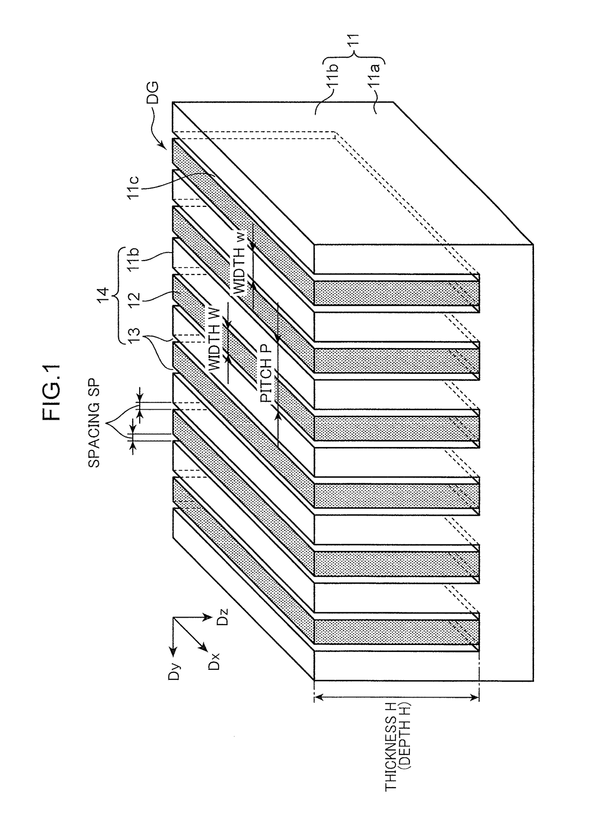
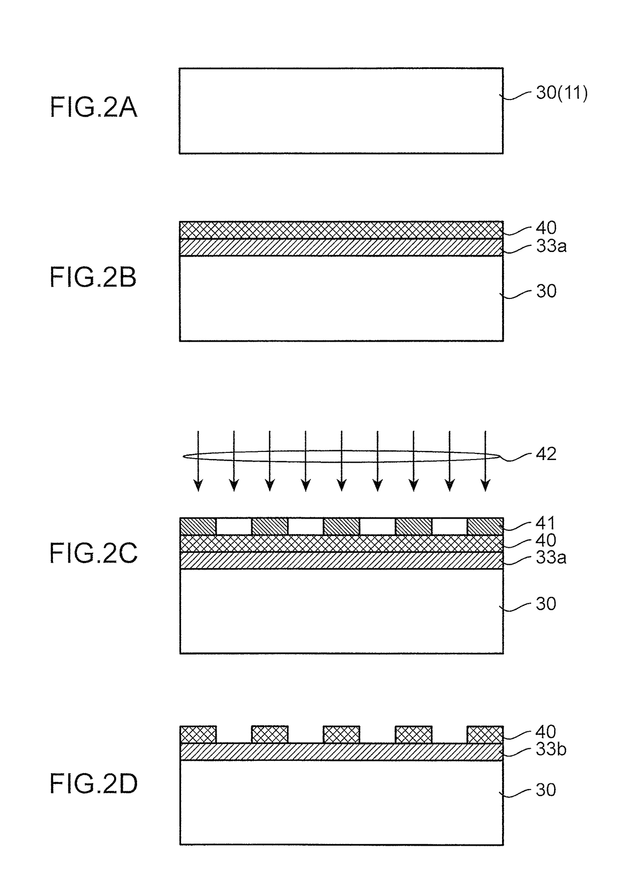
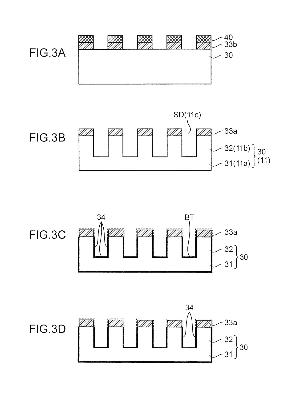
[0032]FIG. 1 is a perspective view depicting a configuration of an X-ray metal grating structure according to a first embodiment of the present invention. FIGS. 2 to 4 are diagrams illustrating a production method for the X-ray metal grating structure according to the first embodiment. FIG. 5 is a perspective view depicting a silicon substrate in a production process of the X-ray metal grating structure according to the first embodiment. FIG. 6 is a diagram illustrating another production method for the X-ray metal grating structure according to the first embodiment.

[0033]As depicted in FIG. 1, the X-ray metal grating structure DG according to this embodiment includes a grating-forming workpiece 11 having one surface formed with a grating region 14 in which a plurality of structural portions 11b mutually having the same shape are periodically provided. The grating region 14 includes: the plurality of structural portions 11b; a remaining portion 12 as a...

second embodiment

; X-ray Metal Grating Unit

[0083]In many cases, an X-ray metal grating structure DG is produced using a silicon wafer (silicon substrate) capable of being fabricated using microfabrication techniques which have been almost established, as mentioned above. From a viewpoint of easiness in sourcing, sourcing cost and others, the silicon wafer is preferably a commonly-used 6 inch-diameter (φ6 inch) type. An X-ray metal grating structure DG fabricatable from such a 6 inch-diameter slicing wafer has a square shape, about 10 cm on a side (□ about 10 cm), and a grating area of □ 10 cm or less. An X-ray metal grating unit DGU according to the second embodiment is directed to resolving restrictions on the grating area.

[0084]FIG. 13 is a diagram depicting a configuration of the X-ray metal grating unit according to the second embodiment. As depicted in FIG. 13, the X-ray metal grating unit DGU according to the second embodiment includes a plurality of X-ray metal grating structures DG arranged ...

third and fourth embodiments

lbot-Lau Interferometer

[0088]In a refraction grating used in an X-ray Talbot interferometer or Talbot-Lau interferometer, it is necessary that a plurality of structural portions are periodically provided with a period of several μm to several ten μm. For this reason, the production method for the X-ray metal grating structure DG according to this embodiment (including any modification thereof) is suitable for production of a metal grating structure used in an X-ray Talbot interferometer or Talbot-Lau interferometer having such micro-sized periodical structural portions. The following description will be made about an X-ray Talbot interferometer or Talbot-Lau interferometer using an X-ray metal grating structure DG produced by the above production method, or the X-ray metal grating unit DGU according to the second embodiment, including a plurality of the X-ray metal grating structures DG.

[0089]FIG. 14 is a perspective view depicting a configuration of an X-ray Talbot interferometer a...


PUM

PropertyMeasurementUnit
transmittanceaaaaaaaaaa
thicknessaaaaaaaaaa
thicknessaaaaaaaaaa

Abstract

An X-ray metal grating structure of the present invention has a grating region in which a plurality of first structural portions are periodically provided, wherein an air gap is formed between each of the plurality of first structural portions and a second structural portion as a remaining part of the grating region other than the plurality of first structural portions. Thus, the X-ray metal grating structure of the present invention is formed as a grating structure having high flatness. A production method therefor comprises a step of forming the air gap between the first structural portion and the second structural portion. Thus, the production method makes it possible to produce an X-ray metal grating structure having high flatness. The present invention further provides an X-ray metal grating unit and an X-ray imaging device each comprising the X-ray metal grating structure.

Description

RELATED APPLICATIONS[0001]This is a U.S. National Phase Application under 35 USC 371 of International Application PCT / JP2014 / 069517 filed on Jul. 24, 2014.[0002]This application claims the priority of Japanese application no. 2013-199968 filed September 26, the entire content of which is hereby incorporated by reference.TECHNICAL FIELD[0003]The present invention relates to an X-ray metal grating structure in which a plurality of structural portions mutually having the same shape are periodically arranged, and an X-ray metal grating structure production method for producing the X-ray metal grating structure. The present invention also relates to an X-ray metal grating unit constructed by arranging a plurality of the X-ray metal grating structures side-by-side, and an X-ray imaging device using the X-ray metal grating structure or the X-ray metal grating unit.BACKGROUND ART[0004]In the case of a one-dimensional structure, a diffraction grating is utilized in optical systems of various...

Claims


Application Information

Patent Timeline
Patent Type & Authority Patents(United States)
IPC IPC(8): A61B6/00G01N23/04G02B5/18G21K1/06G01N23/20
CPCG21K1/06A61B6/484G01N23/04G01N23/20075G02B5/1838G21K2207/005A61B6/4035A61B6/4291G01N2223/064
Inventor YOKOYAMA, MITSURU
Owner KONICA MINOLTA INC
Why Eureka
Try Eureka