Anti-gas lock valve for a reciprocating downhole pump

a technology of anti-gas lock valve and pump, which is applied in the direction of mechanical equipment, liquid fuel engines, fluid removal, etc., can solve the problems of reducing efficiency, reducing and increasing the lifting cost of liquid to the surface, so as to improve the efficiency of the pump and reduce maintenance costs , the effect of increasing production

Active Publication Date: 2019-01-08
INNOVATIVE OILFIELD CONSULTANTS
View PDF31 Cites 6 Cited by
  • Summary
  • Abstract
  • Description
  • Claims
  • Application Information

AI Technical Summary

Benefits of technology

[0025]Using embodiments disclosed herein reciprocating pump efficiency is improved, with increased production and reduced maintenance. Production is increased as gas-locking is reduced or when it occurs is quickly overcome to resume liquid production. Maintenance is reduced through elimination of the damaging technique of tapping bottom, mitigating damage to valve balls, cages and seats. Rod life is increased through the reduction in rod slap.
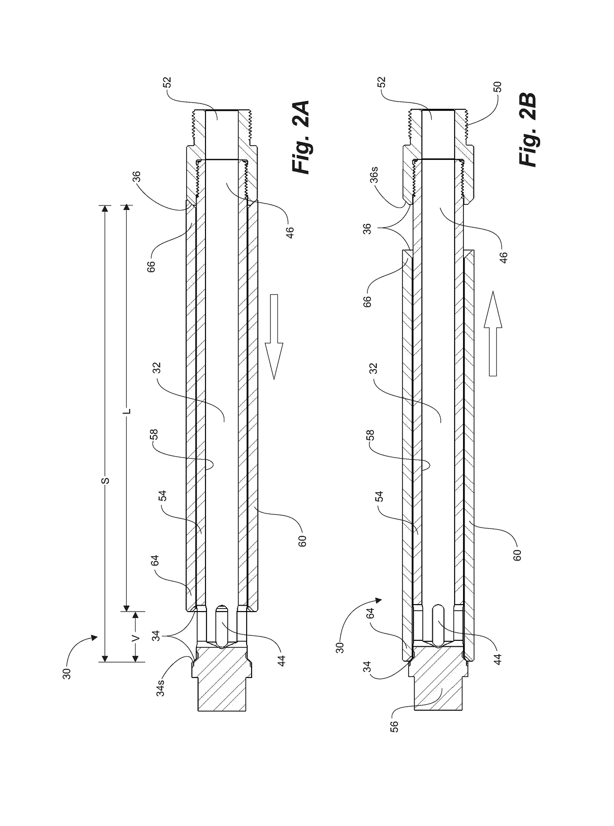
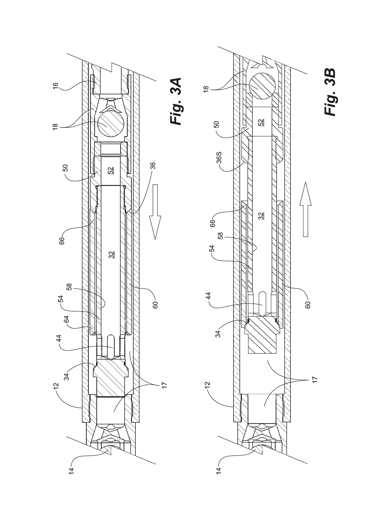
[0026]Lazy operation of prior art travelling valves, in gas-locking situations, is overcome using a pre-valve that is positively actuated to incrementally compress fluids in the pump chamber below the travelling valve and improve the effectiveness of fluid uptake during each cycle, until such time as sufficient pressure is developed to open the travelling valve against hydrostatic pressure thereabove. The pre-valve is operational, not by mere differential pressures thereacross, but by a drag sleeve, actuated by the mechanical motion of the plunger to which it is attached. Accordingly, the pre-valve is not dependent upon differential pressures thereacross to open. Each cycle, by sealably retaining at least a portion of compressed gassy fluids in the pre-valve on each upstroke, the volumetric effectiveness of the pump's upstroke is improved for drawing incremental charges of fluid into the pump chamber and incremental increases in pump chamber pressure until the travelling valve opens and normal pumping resumes

Problems solved by technology

Gas takes the place of liquid in the compression chamber, reducing efficiency.
The presence of gas in the compression chamber reduces the efficiency of the pump, and lifting costs to produce the liquid to the surface are increased.
Hitting the pump to open the valves causes damage to pump components and the rod string.
Operating the pump in a gas locked condition is undesirable because energy is wasted in that the pump is reciprocated but no fluid is lifted.
The pump, sucker rod string, surface pumping unit, gear boxes and beam bearings can experience mechanical damage due to the downhole pump plunger hitting the liquid-gas interface in the compression chamber on the downstroke.
Loss of liquid lift leads to rapid wear on pump components, as well as stuffing box seals.
Gas-locking, and implementation of a prior art solution for overcoming same, not only damages the pump and stuffing box, but can reduce the overall productivity of the well.
Still another problem arises in the Texas Panhandle of the United States, where some oil fields have a minimum gas-to-oil ratio production requirement.
Many gas wells are unable to produce gas at their full potential because the downhole pumps are unable to lift the liquid oil, as the pumps are essentially gas locked.
Still another problem arises in stripper wells, which are wells that produce ten barrels or less of liquid each day.
Separation equipment, which separates the gas from the well, is not used because the production volume is too low to justify the expense of separation equipment.
The gas is vented off of the stock tank into the atmosphere, contributing to air pollution and a waste of natural gas.
Still another problem arises in wells with little or no “rat hole”.
Conventional downhole pumps cannot pump these wells to their full potential due to the low working submergence of the pump in the fluid.
But, in wells with little or no rat hole, shutting the pump off has no effect because the liquid level is low.
Deepening the well bore is typically too expensive.
These wells contain oil, but cannot be produced with prior art pumps.
Thus, gas located between the traveling check valve and the standing check valve can merely compress during the down stroke without generating sufficient pressure to open the traveling valve.
This problem is aggravated in large bore pumps, where considerably more internal volume is available for gas accumulation, with concomitant low pressurization during compression.
Furthermore, the fluid reservoir characteristics of such formations change with time, requiring constant adjustments to the pump installations.
Applicant has found that the annulus method of preventing gas from reaching the pump is neither practical nor effective.
Such failure to completely fill the chamber is attributed to various causes.
If this interface is relatively high in the chamber, gas interference results.
The change in resistances causes a mechanical shock or jarring.
Such a shock damages the pump, the sucker rods and the tubing.
If the liquid-to-gas interface is relatively low in the chamber, gas lock results, wherein insufficient pressure is built up inside of the chamber on the downstroke to open the plunger valve.
The plunger is thus not charged with fluid and the pump is unable to lift anything.
A gas locked pump, and its associated sucker rods and tubing, may experience damage from the plunger hitting the interface.
However, with a pump off condition, the low head pressure is unable to force enough fluid to completely fill the chamber.
A pump (and its associated equipment) that is in a pump off condition suffers mechanical shock and jarring as the plunger passes through the liquid-to gas interface.
A restricted intake can also cause pump off.
As set forth above, there are a number of problems that are regularly encountered during oil pumping operations.
With the balls unable to unseat, pumping comes to a halt with reduction or cessation of liquid production and other related issues including dry stuffing box failures.
This can be time-consuming and, of course, interrupts pumping operations.
The adjustment of the pump requires a service visit and the extent of the tap is not always appreciated at surface when the impact actually occurs one or more kilometers downhole.
The usual result is damage to the sucker rods, rod guides, pump plunger and barrel.

Method used


Image

  • Anti-gas lock valve for a reciprocating downhole pump
  • Anti-gas lock valve for a reciprocating downhole pump
  • Anti-gas lock valve for a reciprocating downhole pump

Examples


Embodiment Construction

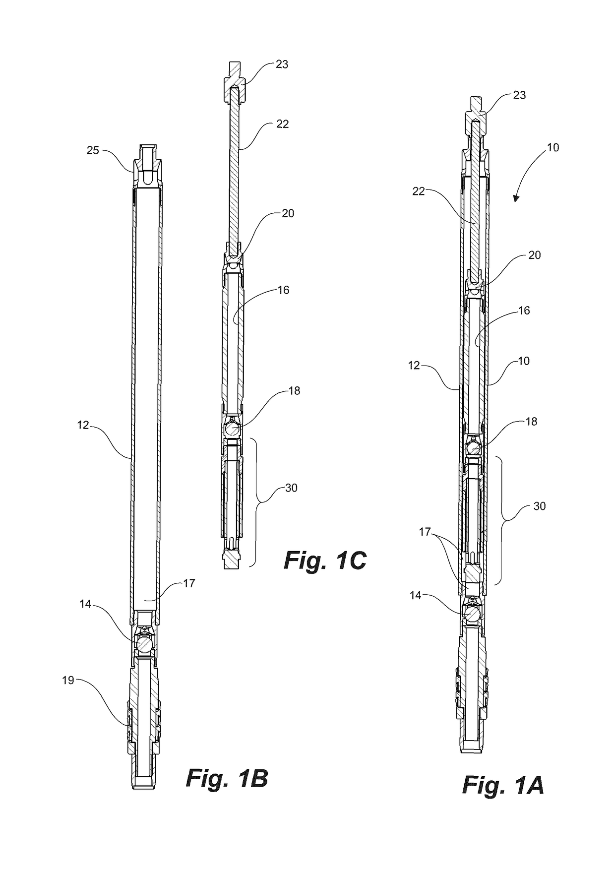
[0041]With reference to FIGS. 1A, 1B and 1C, a typical reciprocating plunger pump 10 comprises a barrel 12, typically about 20 feet in length, fluidly connected to the bore of a tubing string (not shown) extending from a hydrocarbon formation and uphole to surface, the barrel 12 having a standing valve 14 at a bottom or downhole end. A plunger 16, in the order of about four or five feet in length, has a travelling valve 18 at a downhole end thereof. As is conventional, the pump 10 is secured in the tubing string with either or both a top or bottom hold-down 19 between the pump 10 and a seating nipple in the tubing string. Further, the hold-down 19 seals the pump 10 within the tubing string.

[0042]Simply, a fluid pump has barrel 12 and the plunger 16 within that reciprocates uphole on an upstroke to draw a charge of fluid from the formation into a pump chamber 17, to charge the pump barrel 12 with fluid, and downhole on a downstroke to transfer the fluid into the hollow plunger 16 for...


PUM


Abstract

Method and apparatus overcoming gas-lock in reciprocating downhole pumps. On the downstroke of a plunger in a barrel, gassy fluid is compressed in the pump chamber between standing and travelling valves. Downhole plunger movement drags a sleeve over a mandrel for opening a chamber valve to a staging chamber located at a downhole end of the travelling valve for receiving at least a portion of the compressed and gassy fluid therein. On the upstroke, the chamber valve is dragged closed for sealably retaining the compressed gassy fluid therein while drawing an additional increment of fluid through the standing valve into the pump chamber. Continued downstroke and upstroke cycles increases pressure of the compressed gassy fluid in the pump chamber until it exceeds the hydrostatic head above the travelling valve for resumption of normal fluid pumping.

Description

FIELD OF THE INVENTION[0001]This invention relates to downhole reciprocating pumps and more particularly to apparatus to minimize or overcome gas-locking.BACKGROUND OF THE INVENTION[0002]When an oil well is first drilled and completed, the fluids (such as crude oil) may be under natural pressure which is sufficient to produce on its own. In other words, the oil rises to the surface without any assistance.[0003]In many oil wells, and particularly those in fields that are established and aging, natural pressure has typically declined to the point where the oil must be artificially lifted to the surface. Subsurface pumps are located in the well below the level of the oil. A string of sucker rods extends from the pump up to the surface to a pump jack device, or beam pump unit. A prime mover, such as a gasoline or diesel engine, or an electric motor, on the surface causes a pivoted walking beam of a pump jack to rock back and forth, one end connected to a string of sucker rods for moving...

Claims


Application Information

Patent Timeline
Patent Type & Authority Patents(United States)
IPC IPC(8): F04B47/00F04B47/02F04B19/22F04B17/00F04B23/02F04B39/08F04B53/10E21B34/00E21B43/12F04B7/00E21B34/12F04B53/12
CPCF04B47/00E21B34/12E21B43/126E21B43/127F04B7/008F04B7/0069F04B23/023F04B39/08F04B47/02F04B53/1005F04B53/12F04B19/22F04B2205/503E21B2034/007E21B2200/06
Inventor DOWNING, DONALD R
Owner INNOVATIVE OILFIELD CONSULTANTS
Why Eureka
Try Eureka