
Microfluidic device for full blood count

a microfluidic device and full blood count technology, applied in the field of microfluidic methods and devices, can solve the problems of inability to accurately measure the blood count, and high cost of the device, so as to reduce the amount of reagent used, reduce the overall device cost, and reduce the effect of dilution

Active Publication Date: 2019-01-29
KONINK PHILIPS ELECTRONICS NV
View PDF21 Cites 0 Cited by
  • Summary
  • Abstract
  • Description
  • Claims
  • Application Information

AI Technical Summary

Benefits of technology

This patent describes a device that can detect different particles, particularly red blood cells with different properties using both optical and impedance measurement means. The device also includes a micro fluidic dilulator to enable large dilutions to be performed, reducing the amount of reagent and time needed for the procedure. This makes the device suitable for use in a point of care haematology analyser where the quantity of red blood cells within the blood makes large dilution necessary. Overall, the device has the technical effects of improved accuracy in detecting different particles and a more efficient and cost-effective way of performing dilutions.

Problems solved by technology

The high cost and complexity of these devices, coupled to the need for venous blood, means that they are mostly large scale, centralized facilities.
Drabkin's reagent contains Potassium Cyanide, which is extremely toxic.
This large dilution causes an inherent imprecision in the method.
Finally, in some pathological samples, turbidity can lead to erroneously high absorption readings, which in turn will give rise to an incorrect Hb concentration.
However, none of the above described devices and techniques are capable of measuring all parameters that are required for an FBC at ones.
In other words, none of the devices and techniques described above are able to perform a complete FBC test at the point of care.

Method used


Image

  • Microfluidic device for full blood count
  • Microfluidic device for full blood count
  • Microfluidic device for full blood count

Examples


Embodiment Construction

[0072]The present invention will be described with respect to particular embodiments and with reference to certain drawings but the invention is not limited thereto but only by the claims. The drawings described are only schematic and are non-limiting. In the drawings, the size of some of the elements may be exaggerated and not drawn on scale for illustrative purposes. The dimensions and the relative dimensions do not correspond to actual reductions to practice of the invention.

[0073]Furthermore, while some embodiments described herein include some but not other features included in other embodiments, combinations of features of different embodiments are meant to be within the scope of the invention, and form different embodiments, as would be understood by those in the art. For example, in the following claims, any of the claimed embodiments can be used in any combination.

[0074]The present invention provides a microfluidic device for full blood count (FBC), a method for forming suc...


PUM

PropertyMeasurementUnit
volumeaaaaaaaaaa
flow rateaaaaaaaaaa
flow rateaaaaaaaaaa

Abstract

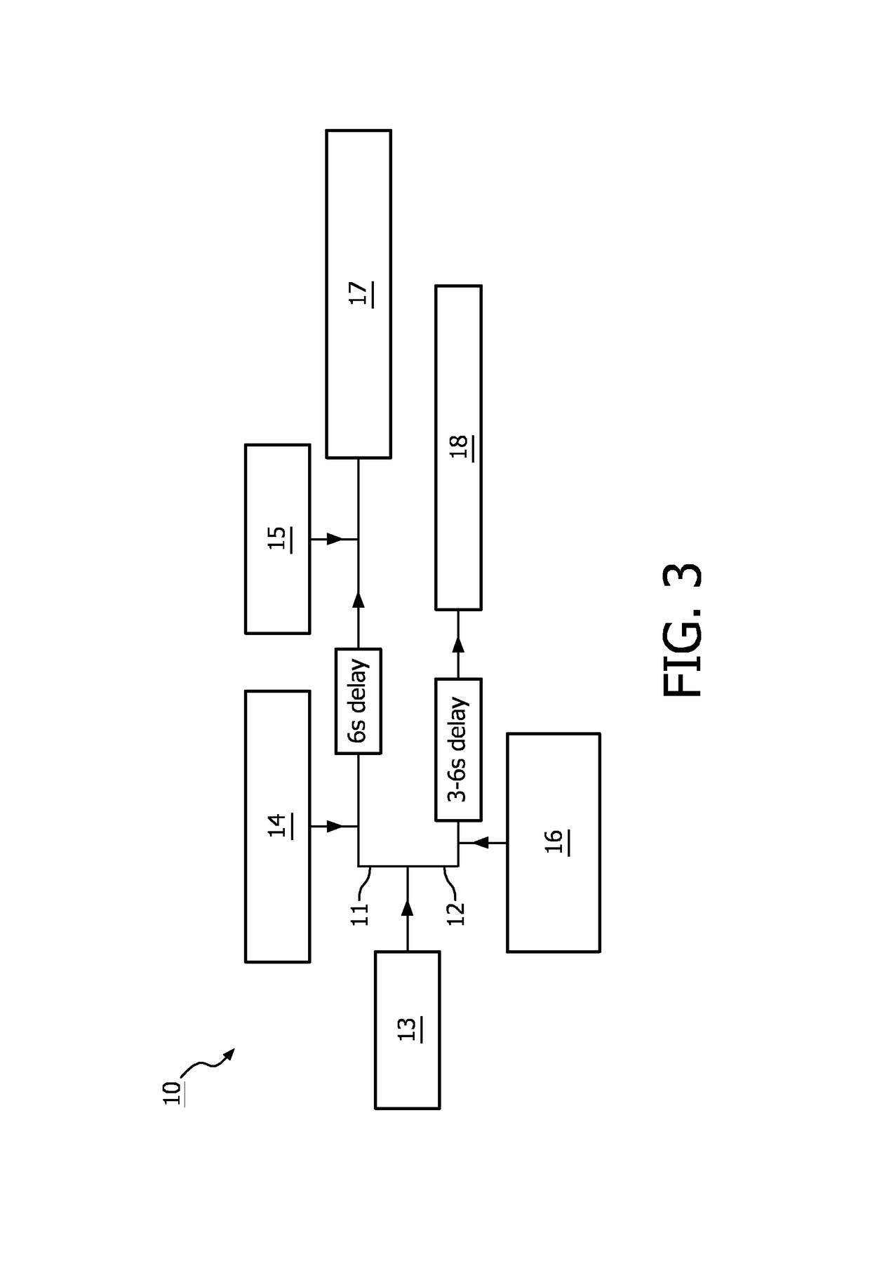
A device for full blood count includes first channel and second channels separated from each other. The device further includes a first inlet configured to provide a whole blood sample to the first and second channels, a second inlet configured to provide a lysis agent for white blood cell count in to the first channel, a third inlet configured to provide a quench solution to the first channel, and a fourth inlet configured to provide a lysis agent for hemoglobin measurement to the second channel.

Description

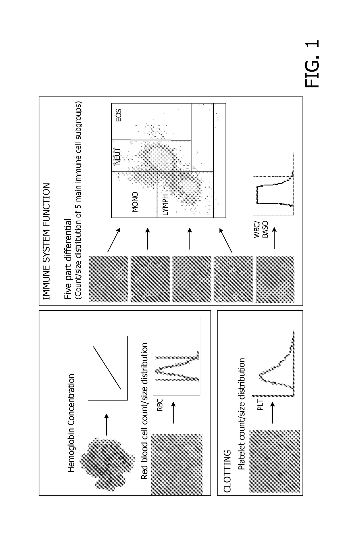
FIELD OF THE INVENTION[0001]The present invention relates to microfluidic methods and devices. More particularly, the present invention relates to a microfluidic device for full blood count (FBC), a method for forming such a micro fluidic device and a method for performing a full blood count test (FBC test) using such a microfluidic device.BACKGROUND OF THE INVENTION[0002]Full blood count (FBC) is a diagnostic test that is used to measure cellular composition of blood. It may give information about the status of an immune system of a patient, about the ability of the blood to disseminate oxygen and / or about the ability of the blood to effectively clot. As such, it is a fundamental test that is often used as an initial “general purpose” diagnostic tool or as a more targeted monitoring solution. Examples of care cycles that include a full blood count as a monitoring tool include oncology, arthritis and Crohn's disease. As many as 300 million FBC tests are performed each year in the de...

Claims


Application Information

Patent Timeline
Patent Type & Authority Patents(United States)
IPC IPC(8): G01N33/569B01L3/00G01N15/12G01N15/14G01N33/72G01N33/80G01N15/00G01N15/10
CPCB01L3/502776G01N33/56972G01N15/12G01N15/1484G01N33/721G01N33/80G01N2015/1037G01N2015/1062Y10T137/0402B01L2200/10B01L2300/0627B01L2300/087B01L2300/0816B01L2300/0864G01N2015/008G01N2015/0069G01N2015/0084G01N2015/011G01N2015/1019G01N2015/018G01N2015/016G01N2015/1024
Inventor PETTIGREW, DAVID M.GWYER, JAMES D.
Owner KONINK PHILIPS ELECTRONICS NV
Learn More