Moving injection gravity drainage for heavy oil recovery

a gravity drainage and heavy oil technology, applied in the field of subterranean hydrocarbon recovery, can solve the problems of low mobility, or even no mobility, in the reservoir under natural conditions, reduce the variability of the flux of injected steam in the sagd, and achieve high total oil recovery factors, reduce air-oil ratios, and high oil production rates

Active Publication Date: 2019-02-19
MARTIN PARRY TECH PTY LTD
View PDF4 Cites 2 Cited by
  • Summary
  • Abstract
  • Description
  • Claims
  • Application Information

AI Technical Summary

Benefits of technology

[0014]An object of the present invention is to provide a method for the recovery of hydrocarbons from subterranean formations, including, for example, heavy oil, oil sands, and bitumen reservoirs. A key feature of these oil formations is that the oil has a relatively high viscosity, which makes it have low mobility, or even no mobility, in the reservoir under natural conditions.
[0016]Processes such as SAGD, work best in formations with low heterogeneity, where the injected fluids can be distributed uniformly over the injection well when being injected into the reservoir. Techniques have been implemented to reduce the variability of the flux of injected steam in SAGD along the horizontal wells when operating in heterogeneous reservoirs, but these are generally only partially successful.
[0022]Another key feature of the present invention is that the location of the combustion fronts established by injecting an oxidant (e.g., air, enriched air or pure oxygen) into the formation are controlled by moving the tubing string located within the completed injection well. The moving of the oxidant injection points enables efficient recovery of in-situ hydrocarbons, as zones with low productivity for hydrocarbon recovery (i.e., those with low permeability, low oil saturation, or zones which are highly fractured) can be skipped, enabling the targeting of those zones with high productivity for oil recovery.
[0023]In addition, by targeting reservoir zones periodically, via moving the oxidant injection points, the surface area of the active combustion front can be controlled, thereby ensuring the oxidant flux is sufficient to maintain the combustion process in the high temperature oxidation (HTO) regime. This ensures that the oxidant is used efficiently to generate heat which warms and mobilises the surrounding oil. Thus, periodically the retraction of the oxidant injection points maintains the surface area of in-situ combustion within an allowable range (i.e., every retraction reduces the in-situ combustion surface area) of oxidant flux, heat flux generated, and heat loss to the formation and overburden.
[0025]The present invention therefore differs markedly in approach to other methods which are aimed at achieving uniform distributions of fluids and / or pressure over the length of the horizontal, with devices such as inflow control devices (ICD). In the present invention, the non-uniform properties of the reservoir are managed by moving the location of the injected fluids in time, and producing from targeted zones that have been heated by the combustion processes resultant from oxidant injection. In this way, higher oil recovery rates can be achieved from the process conducted in a heterogeneous reservoir than via use of competing ISC methods, such as Fire Flood, THAI or CAGD.
[0029]By using the concept of moving injection gravity drainage (MIGD), injecting the oxidant from discrete points along the completed horizontal well and enabling these points to be moved through the formation in time, the minimum oxidant flux to ensure efficient combustion in the HTO mode is readily achieved, and at the same time reservoir heterogeneity can be accommodated through operational changes to oxidant injection rates, oxidant / water injection ratios, and by moving the location of the oxidant injection location once all of the oil in a zone has been mobilised to the completed production well. Applying moving injection gravity drainage thereby leads to a much more efficient method of recovering in-situ hydrocarbons from the subterranean formation. This enables high oil production rates, lower air-oil-ratios (AOR) and high total oil recovery factors from a given formation than can be achieved by methods such as Fire Flood, THAI and CAGD as described in the prior-art.

Problems solved by technology

A key feature of these oil formations is that the oil has a relatively high viscosity, which makes it have low mobility, or even no mobility, in the reservoir under natural conditions.
Techniques have been implemented to reduce the variability of the flux of injected steam in SAGD along the horizontal wells when operating in heterogeneous reservoirs, but these are generally only partially successful.

Method used


Image

  • Moving injection gravity drainage for heavy oil recovery
  • Moving injection gravity drainage for heavy oil recovery
  • Moving injection gravity drainage for heavy oil recovery

Examples


example 1

eous Reservoir Simulations

[0079]The rate of heavy oil production and cumulative oil recovery using a method for recovering petroleum from a hydrocarbon-bearing subterranean formation in accordance with an embodiment of the invention has been modeled in computer simulations and compared / contrasted with the THAI and CAGD processes in a three dimensional model of a Kerrobert oil sands formation with reservoir dimensions of 250 meters by 30 meters by 30 meters, with 5 meter grid blocks. Model parameters are shown in Table 4, below.

[0080]In this Example, the MIGD process is simulated with a single injection point in the horizontal injection well, which is swept through the oil reservoir.

[0081]Reservoir heterogeneity is modelled by randomly assigning a porosity of between 10% and 70% to each grid block cell, while keeping the average reservoir porosity of 32%. The distribution of porosity in the reservoir is not a normal distribution and has a longer tail of smaller porosities than given ...

example 2

nt MIGD Simulations

[0087]A detailed simulation of the invention has been performed to demonstrate the effectiveness of the technique for multi-point air injection, to achieve higher oil production per injection / production well pair. The simulation uses three injection points on the horizontal well by way of demonstration, however it is understood that more or less points can be utilised with the present invention.

[0088]Table 6 provides the geometrical parameters of the selected reservoir, while Table 7 provides the physical parameters. For simulation, the reservoir properties were considered to be homogeneous.

[0089]The simulations were conducted using grid blocks of size 1 meter height, 2 meters width and 2 meters length. Earlier sensitivity studies (not reported) showed that these grid block sizes provided the best compromise between computational speed and model resolution for this Example.

[0090]

TABLE 6Reservoir Geometrical ParametersParameterUnitsValueTVD to top of oil paym760Oil...

example 3

Modelling Sensitivities

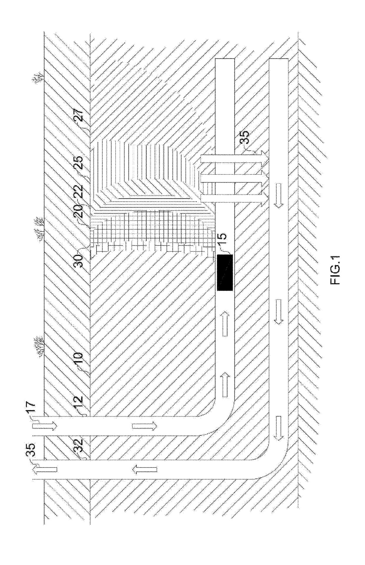
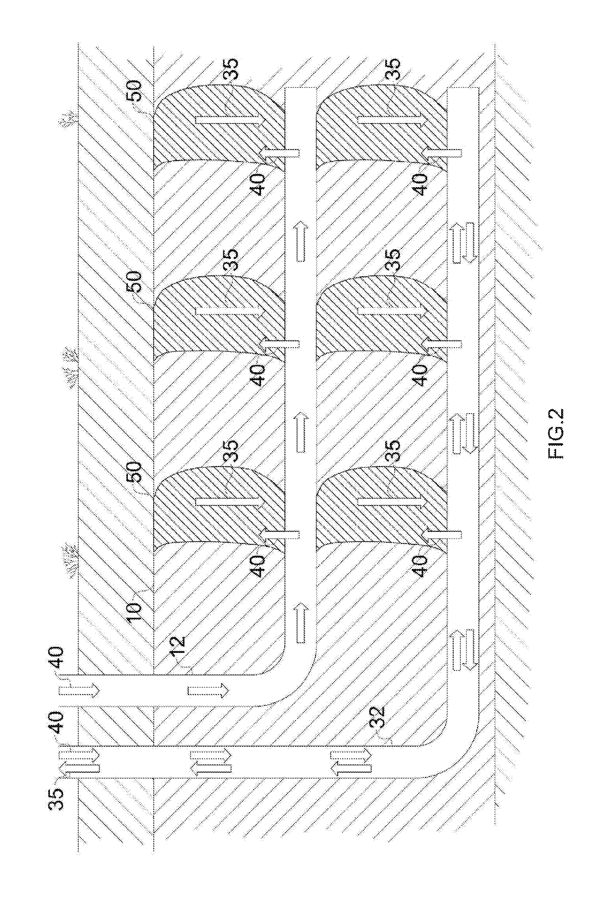
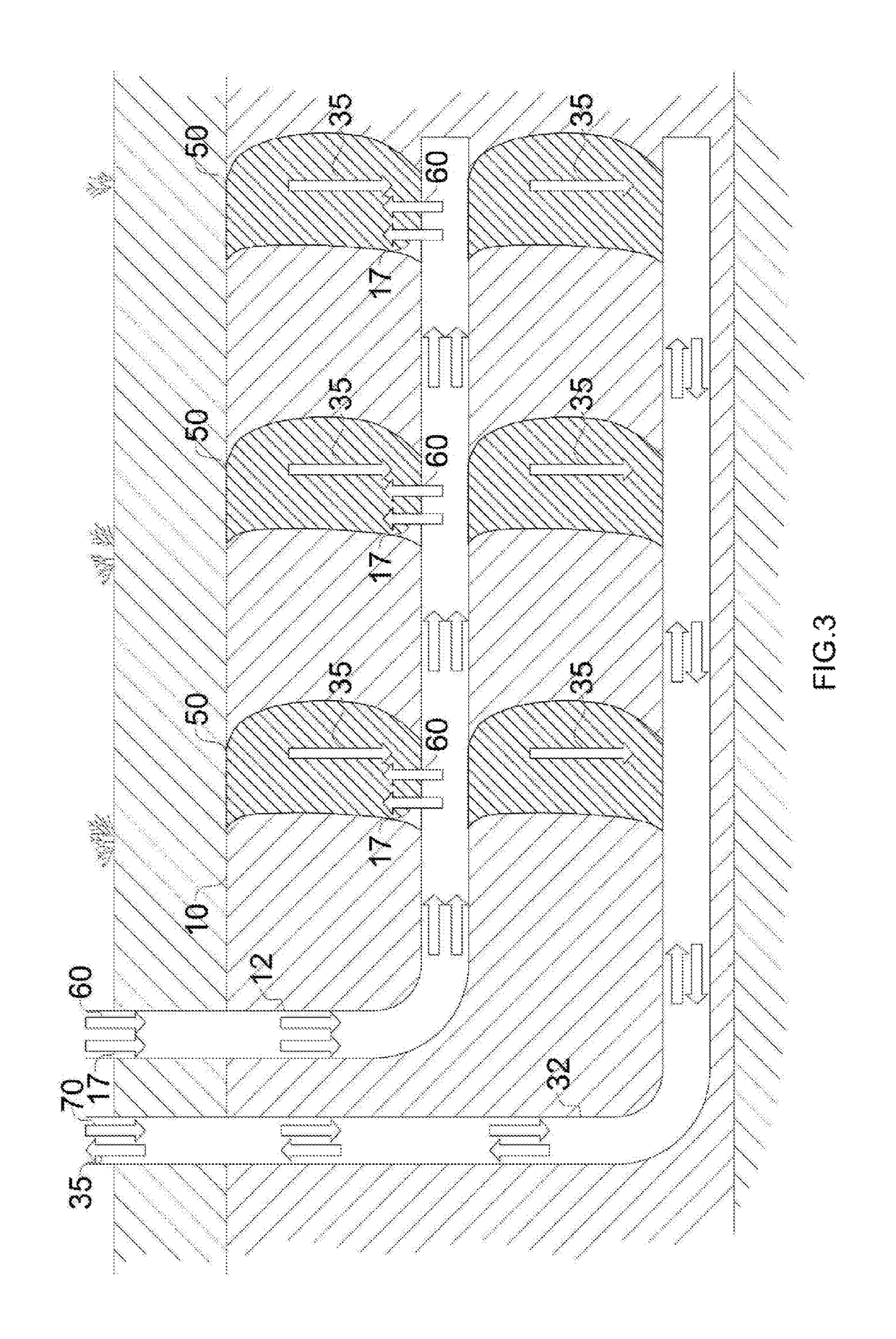
[0107]Reservoir modelling sensitivities for air injection in-situ combustion were carried out, according to the following procedure for steam linking and air injection for recovery of petroleum from a hydrocarbon-bearing subterranean formation, the formation being intersected by a completed well-pair including a generally horizontal injection well and a generally horizontal production well (see, FIGS. 1-5): 1) Start steam circulation (to surface) at the completed production well horizontal at a maximum steam injection flow rate of 4.56 m3 / h (Tubing T1)—steam temperature 320° C. 2) Continue with steam circulation at the completed production horizontal until the production well heel reaches 100° C.—at this temperature the heavy oil flows. 3) Switch from steam circulation to only steam injection with flow being resultant at a maximum well pressure limit of 4000 kPag. 4) Stop steam injection on the completed production well once 4,000 kPag is reached. Allow steam ...


PUM


Abstract

The invention provides methods for mobilizing and recovering petroleum from subterranean formations by in situ combustion.

Description

TECHNICAL FIELD[0001]This invention relates to recovery of hydrocarbons from subterranean formations. In particular, methods for mobilising and recovering petroleum by in-situ combustion are disclosed.BACKGROUND ART[0002]In-situ combustion (ISC) processes are utilised for the purpose of recovering petroleum from heavy oil, oil sands, and bitumen reservoirs. In the process, oil is heated and displaced to a production well for recovery. Historically, in-situ combustion involves providing spaced apart vertical injection and production wells within an underground reservoir. Typically, an injection well is located within a pattern of surrounding production wells. An oxidant, such as air, oxygen enriched air, or oxygen, is injected through the injection well into the reservoir, allowing combustion of a portion of the hydrocarbons in the reservoir in-situ. The heat of combustion and the hot combustion products warm a portion of the reservoir adjacent to the combustion front and displace hy...

Claims


Application Information

Patent Timeline
Patent Type & Authority Patents(United States)
IPC IPC(8): E21B43/24E21B43/243
CPCE21B43/243E21B43/2406
Inventor PERKINS, GREG MARTIN PARRYBURGER, CASPER JAN HENDRIK
Owner MARTIN PARRY TECH PTY LTD
Why Eureka
Try Eureka