Voltage detecting glove

a technology of voltage detection and glove, applied in the field of voltage detection glove and system, can solve the problems of indirect danger, immediate and apparent danger, and even death by electrocution or other deleterious secondary effects

a technology of voltage detection and glove, applied in the field of voltage detection glove and system, can solve the problems of indirect danger, immediate and apparent danger, and even death by electrocution or other deleterious secondary effects

US10247763B1Active Publication Date: 2019-04-02DUPONT SAFETY & CONSTR INC

Image

  • Voltage detecting glove
  • Voltage detecting glove
  • Voltage detecting glove

Examples


example 1

Numerical Simulation of the Effect of a Buffer

[0041]The effect on sensitivity of interposing a low dielectric constant buffer between the antenna and the glove liner, and thereby spacing the antenna away from the wearer's fingers, is simulated numerically, using the circuit 10 of FIG. 4 as a proxy, wherein the various sources of resistance and capacitance are treated as lumped components. In particular, the circuit elements in circuit 10 are as follows:[0042]Vs: AC sinusoidal source, 120 Vrms / 60 Hz[0043]C1: source to antenna capacitance[0044]C2: source to body capacitance[0045]C3: antenna to body capacitance[0046]C4: body to ground capacitance[0047]R1: antenna to body resistance (DC)[0048]R2: body to ground resistance (DC).

[0049]Numerical values of C1 and C2 are calculated as a function of distance between the voltage source and the antenna. C1 was calculated using finite element method (REM) modelling with Comsol Multiphysics Modeling Software (version 5.3, COMSOL, Inc., Burlington...

example 2

Comparative Example 1

Testing of a Voltage-Detecting Glove

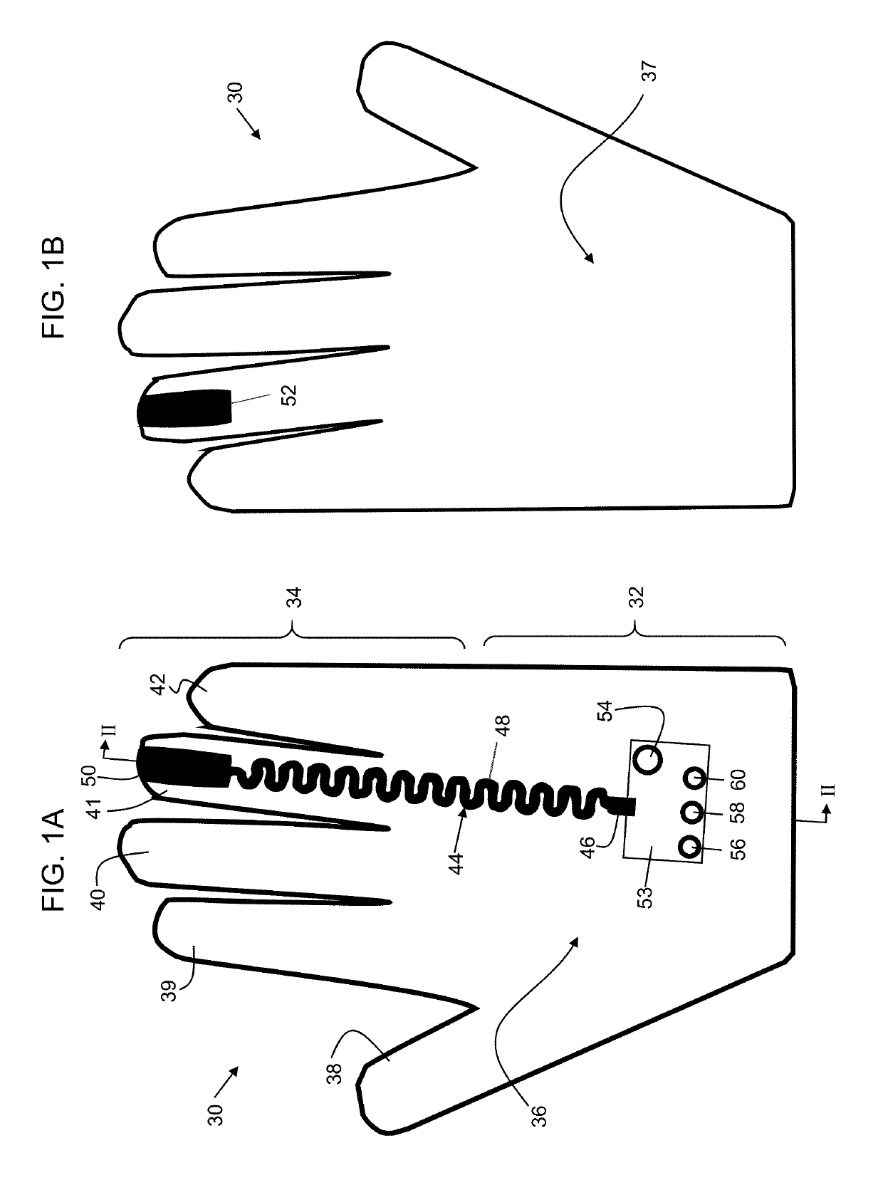
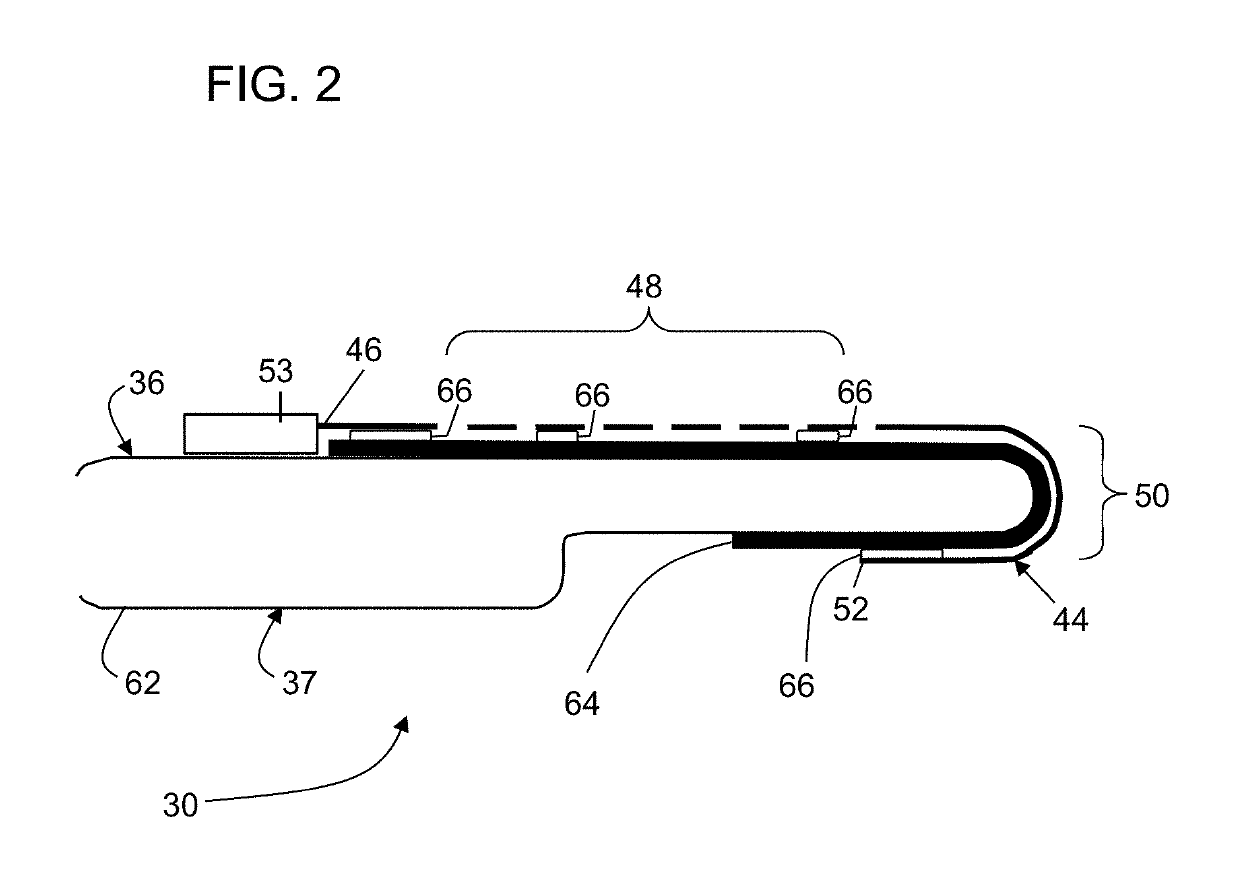
[0057]A voltage-detecting glove was constructed generally in accordance with the description of FIGS. 1-2 above, and thereafter tested to characterize it ability to detect energized AC wiring.

[0058]The glove for Example 2 comprised a glove liner of 0.36 mm-thick Kevlar® para-aramid fiber and a buffer that was fabricated with fire-retardant cotton fabric approximately 3.6 mm thick and shaped to conformally fit a human hand. An antenna was formed of a 12 μm thick Pyralux® polyimide film having a conductive copper layer 12 μm thick and secured to the outside of the inner cotton layer. The antenna extended from a proximal end situated on the back side of the proximal portion 32 and thence along the back side of the third (ring) finger of distal portion 34 in a meander pattern. A solid end section wrapped around the tip of this finger portion and terminated at a distal end on the front side at a location approximately even with the...


PUM


Abstract

A voltage detecting glove comprises a glove liner and an outer glove shell. A conductive antenna is disposed inside the outer glove shell but separated from the glove liner by a buffer. The antenna is connected to electronic circuitry configured to sense a voltage indicative of the proximity of the antenna to an AC electric field resulting from energized AC source, and to activate an alarm if the strength of the field exceeds a preselected threshold limit.

Description

FIELD OF THE INVENTION[0001]The present disclosure relates to a voltage detecting glove and system appointed for use by workers that service electrical equipment or are otherwise likely to encounter energized electrical circuits, and more particularly to a glove that includes an antenna and electronic circuitry capable of detecting an AC electric field and activating a signal in response to the detection of a field exceeding a preselected threshold, so that the worker can be warned of potential danger of shock.TECHNICAL BACKGROUND[0002]Contact with energized electrical circuits and equipment is widely recognized as a serious workplace hazard that can lead to serious injuries and even death by electrocution or other deleterious secondary effects, such as trauma after a fall. In some instances, the hazard is immediate and apparent, but in others, the danger may be indirect. For example, there is an immediate and recognizable hazard for electricians or other workers who deliberately co...

Claims


Application Information

Patent Timeline
02 Apr 2019
Publication
US10247763B1
IPC
G01R19/155; G01R19/165; G08B21/18; A41D19/00; A41D19/015; G08B21/02
CPC
G01R19/155; G01R19/16547; G08B21/02; A41D19/01529; A41D19/01594; A41D19/001; G08B21/182; G01R19/16595
Inventors
WU, WEI; BLACKMAN, GREGORY SCOTT