Highly pure powder intended for thermal spraying

a technology of thermal spraying and high purity, applied in the field of powder, can solve the problems of releasing particles when exposed to corrosive environments, fine powders obtained directly by chemical or pyrolytic manufacturing processes are not suitable for plasma spraying, and dense liner by thermal spraying, so as to improve the purity of feed powder

Active Publication Date: 2019-04-09
SAINT GOBAIN CENT DE RES & DEVS & DETUD EUROEN
View PDF13 Cites 1 Cited by
  • Summary
  • Abstract
  • Description
  • Claims
  • Application Information

AI Technical Summary

Benefits of technology

[0037]Preferably, there is no intermediate consolidation stage and in particular no sintering stage between stages a) and b). This absence of intermediate consolidation stage advantageously improves the purity of the feed powder.

Problems solved by technology

For example, the very fine powders obtained directly by chemical or pyrolytic manufacturing processes are not suitable for plasma spraying without an additional stage of consolidation in order to form larger (and porous) agglomerates, in particular sintered agglomerates.
In particular, the sintered powders described in U.S. Pat. No. 6,916,534, US2007 / 077363 or US2008 / 0112873 cannot result in a very dense liner by thermal spraying.
Furthermore, the liners obtained from porous agglomerates result, over time, in the release of particles when they are exposed to corrosive environments.
In the abovementioned application, the powders obtained by grinding a molten mass are not appropriate either, because of the impurities which are added during the grinding stage.
However, they have a high melting temperature and a low thermal diffusion.
It is thus difficult to obtain a very dense liner starting from these particles by plasma spraying.

Method used


Image

  • Highly pure powder intended for thermal spraying
  • Highly pure powder intended for thermal spraying
  • Highly pure powder intended for thermal spraying

Examples


examples

[0147]The following examples are provided for the purposes of illustration and do not limit the scope of the invention.

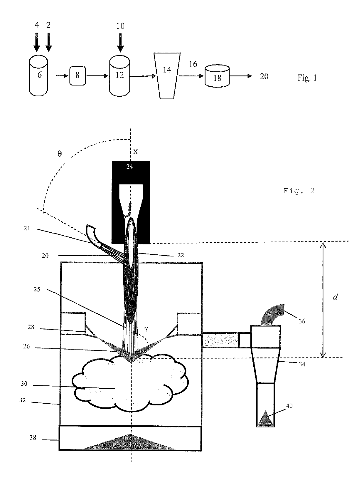
[0148]The feed powders I1 to I5, C1 and C2 were manufactured according to the invention with a plasma torch similar to the plasma torch represented in FIG. 2, starting from a source of pure Y2O3 powder having a median diameter D50 of 1.2 microns, measured with a Horiba laser particle analyzer, and a chemical purity of 99.999% of Y2O3.

[0149]In stage a), a binder mixture is prepared by addition of PVA (polyvinyl alcohol) binder 2 to deionized water 4. This binder mixture is subsequently filtered through a 5 μm filter 8. Yttrium oxide powder 10 is mixed into the filtered binder mixture in order to form a slip 12. The slip is prepared so as to comprise a percentage by weight, 55% of yttrium oxide and 0.55% of PVA, the remainder to 100% being deionized water. The slip is intensively mixed using a high shear speed mixer.

[0150]The granules G3 and G6 were subsequently obtai...


PUM

PropertyMeasurementUnit
median particle size D50aaaaaaaaaa
sizeaaaaaaaaaa

Abstract

Powder of particles, more than 95% by number of said particles exhibiting a circularity greater than or equal to 0.85, wherein said powder contains more than 99.8% of a rare earth oxide and / or of hafnium oxide and / or of yttrium aluminum oxide, as percentage by weight relative to the oxides, and has: a median particle size D 50 of between 10 and 40 microns and a size dispersion index (D 90−D 10) / D 50 of less than 3; a percentage by number of particles having a size less than or equal to 5 μm which is less than 5%; an apparent-density dispersion index (P<50−P) / P of less than 0.2, the cumulative specific volume of the pores which have a radius of less than 1 μm being less than 10% of the apparent volume of the powder, in which the percentiles Dn of the powder are the particle sizes corresponding to the percentages, by number, of n %, on the curve of cumulative distribution of the particle size of the powder, the particle sizes being classified in increasing order, the density P<50 being the apparent density of the fraction of particles having a size less than or equal to D50, and the density P being the apparent density of the powder.

Description

TECHNICAL FIELD[0001]The invention relates to a powder capable of being deposited by plasma, to a process for manufacturing such powder and to a liner obtained by plasma spraying of said powder.STATE OF THE ART[0002]The internal surfaces of chambers used to treat (for example by plasma etch) semiconductors, for example silicon wafers, are conventionally protected with a ceramic liner applied by plasma spraying. This liner has to be highly resistant to halogen-comprising plasmas or to highly corrosive environments. Plasma spraying requires, as feed powder, a powder exhibiting a good fluidity and a particle morphology which makes possible appropriate heating during the spraying. In particular, the size of the particles has to be sufficient for the particles to penetrate the plasma and to limit the losses by vaporization.[0003]For example, the very fine powders obtained directly by chemical or pyrolytic manufacturing processes are not suitable for plasma spraying without an additional ...

Claims


Application Information

Patent Timeline
Patent Type & Authority Patents(United States)
IPC IPC(8): C01F17/00C01G27/02B05B7/22B65D25/14C23C4/11C23C4/134C01F17/212C01F17/218C01F17/224
CPCC01F17/0043B05B7/22B65D25/14C01F17/0018C01G27/02C23C4/11C23C4/134C01P2006/80C01P2004/54C01P2004/60C01P2004/61C01P2006/10C01P2006/12C01P2006/14C01F17/32C01F17/218C01F17/212C01F17/224
Inventor BILLIERES, DOMINIQUEALIMANT, ALAINWALLAR, HOWARD
Owner SAINT GOBAIN CENT DE RES & DEVS & DETUD EUROEN
Why Eureka
Try Eureka