Monolithically integrated three electrode CMUT device

a three-electrode cmut, monolithic technology, applied in mechanical vibration separation, medical science, diagnostics, etc., can solve the problem of limiting the performance of the array, and achieve the effect of improving and efficient high-voltage supply

Active Publication Date: 2019-04-23
KONINKLJIJKE PHILIPS NV
View PDF18 Cites 2 Cited by
  • Summary
  • Abstract
  • Description
  • Claims
  • Application Information

AI Technical Summary

Benefits of technology

[0011]It is an object of present invention to provide a capacitive micromachined ultrasonic transducer cell of the kind set forth in the opening paragraph which enables an improved and efficient high voltage supply to the CMUT array which is more suitable for miniaturization.
[0018]This condition is a consequence of the requirements to the capacitive relation between the second and the third electrodes. In order to keep this capacitance above the CMUT's capacitance the dielectric layer may be material with a high dielectric constant (so called high-k dielectrics). This will also allow avoiding leakage currents between the electrodes and achieving stability in the CMUT's operation. Since leakage currents are not desirable, nor is breakdown, a limitation may be put on reducing dielectric thickness (it is desired to withstand the applied bias voltage) and therefore it will limit the ratio of the capacitances (Cc / Cf).
[0020]The DC bias voltage is provided via the separate third electrode, while the signal transmitter / receiver (provided through the ASIC electronics) can drive and / or sense via coupling to the separate signal (first and second) electrodes. This electrode's configuration allows separating a DC bias component from the signal component. As a result the high voltage requirements of the ASIC technology can be reduced in case both the first and second electrodes are actively controlled. This also allows exploiting the advantages of driving the CMUT cell from both sides.
[0022]This embodiment enables a fully integrated RC filter into the CMUT cell. The capacitive component is implemented through the dielectric layer in between the second electrode and the third electrode, while the high impedance component is implemented through the resistor connected in series with the third electrode and via which the DC voltage can be applied. Therefore, in this embodiment every transducer CMUT cell may have its own high impedance shielding resistor inside the bias-node connection. This results in a “failing cMUT cell” not causing large shortcut currents and therefore not causing breakdown of the whole array of the connected ASIC.
[0024]This embodiment explores an opportunity of driving each CMUT cell in the probe via both the first and second electrodes in an array. Interconnecting of the first electrodes in the first sub-group and the second electrodes in the second sub-group provides a possibility of using the same CMUT cell for both sub-groups and ability to drive each sub-group individually.
[0025]In yet another embodiment of the present invention the third electrodes of the CMUT cells in array are connected to the same DC bias voltage source via series resistors Applying the same DC bias voltage source simplifies the electronic interconnects in the probe and permits further scaling down of the ultrasound probe's dimensions.

Problems solved by technology

Further, parasitic effects of these discrete components may limit the performance of the array.

Method used


Image

  • Monolithically integrated three electrode CMUT device
  • Monolithically integrated three electrode CMUT device
  • Monolithically integrated three electrode CMUT device

Examples


Embodiment Construction

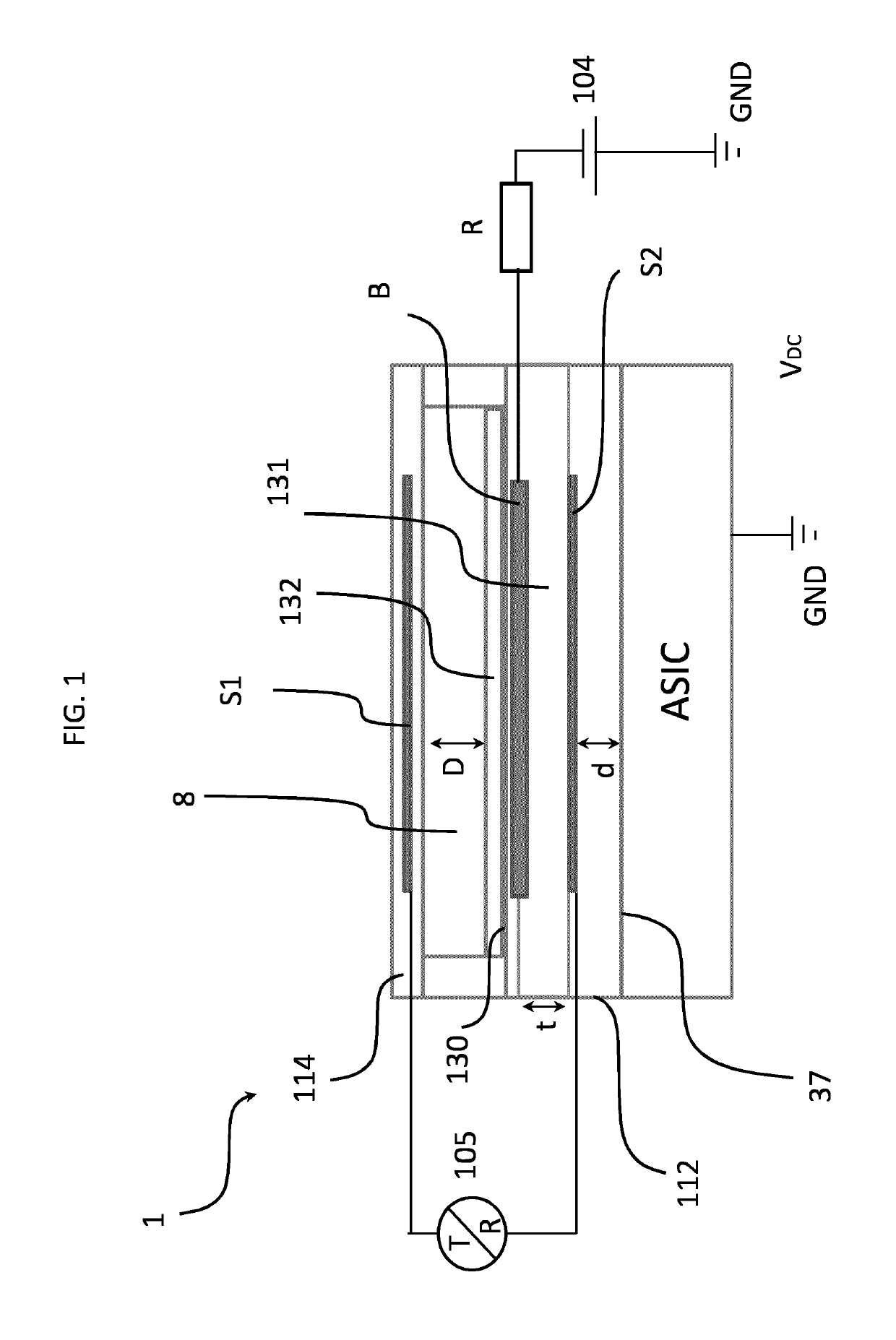
[0036]In an implementation of the present invention the elements of an ultrasound transducer array 10′ (FIG. 8) comprise CMUT cells. FIG. 1 shows an embodiment of a CMUT cell 1 according to the invention. A flexible membrane or diaphragm 114 is suspended above (or oppossing) a substrate 112 with a gap 8 there between. The substrate can be made of either silicon or another CMOS compatible material such as glass. A first electrode S1 is coupled to the cell membrane 114 and can move with the membrane 114. In the embodiment shown in FIG. 1 a third electrode B is embedded into the floor 130 of the cell comprising an upper surface of the substrate 112. Other realizations of the electrode S1 design can be considered, such as electrode S1 may be embedded in the membrane 114 or it may be deposited on the membrane 114 as an additional layer. In this example, the bottom electrode B is circularly configured and embedded into the cell floor 130. In addition, the membrane layer 114 is fixed relat...


PUM


Abstract

A capacitive micromachined ultrasonic transducer (CMUT) cell comprising three electrodes: a first electrode coupled to a cell membrane; a second electrode embedded into a cell floor opposing the first electrode and separated therefrom by a gas or vacuum cavity; and a third electrode opposing the second electrode on the cavity side, wherein a dielectric layer is sandwiched between the second electrode and the third electrode to create a capacitive relation between the second electrode and the third electrode. The three electrode CMUT cell provides an ultrasound transducer with two actively driven (controlled) electrodes.

Description

[0001]This application is the U.S. National Phase application under 35 U.S.C. § 371 of International Application No. PCT / EP2014 / 076475, filed on Dec. 4, 2014, which claims the benefit of European Application Serial No. 13196881.0, filed Dec. 12, 2013. These applications are hereby incorporated by reference herein.FIELD OF THE INVENTION[0002]This invention relates to a capacitive micromachined ultrasonic transducer (CMUT) cell comprising a substrate, a cell membrane opposing the substrate with a gap there between, a first electrode coupled to the cell membrane, a second electrode embedded into a cell floor opposing the first electrode and separated therefrom by a gas or vacuum cavity, wherein the cell floor comprises an upper surface of the substrate. Further this invention relates to a probe comprising an array of the CMUT cells according to the present invention, and an ultrasonic imaging system comprising such the probe according to the present invention.BACKGROUND OF THE INVENTIO...

Claims


Application Information

Patent Timeline
Patent Type & Authority Patents(United States)
IPC IPC(8): B06B1/02A61B8/00
CPCB06B1/0292A61B8/4444A61B8/4494B06B2201/20
Inventor VAN RENS, ANTONIA CORNELIAGROENLAND, ALFONS WOUTER
Owner KONINKLJIJKE PHILIPS NV
Why Eureka
Try Eureka