Thermocouple and manufacturing method for same

a manufacturing method and technology of thermocouple, applied in the direction of thermometer details, instruments, heat measurement, etc., can solve the problems of inability to stably use the thermocouple, the thermocouple cannot be stably used under the oxidation atmosphere, and the temperature cannot be precisely measured. to achieve the effect of stably performing

Active Publication Date: 2019-05-07
FURUYA KINZOKU KK
View PDF30 Cites 0 Cited by
  • Summary
  • Abstract
  • Description
  • Claims
  • Application Information

AI Technical Summary

Benefits of technology

[0017]In the thermocouple according to the present disclosure, it is preferable that the insulator is configured such that the content of each element of Al, Fe, Si, and Ti is 100 ppm or less by mass and the content of C is 10 ppm or less by mass. When the thermocouple is used at a high temperature of 1900° C. or higher, durability can be further improved.
[0018]In the thermocouple according to the present disclosure, it is preferable that a surface of the element wires is covered with an oxygen barrier film, and a thickness of the oxygen barrier film is 20 nm or more but 800 nm or less. It is possible to suppress oxidation volatilization or oxidation degradation of the element wires. Furthermore, it is possible to prevent reduction in melting point of the element wires caused by adhesion of impurities decomposed and volatilized from the insulator.
[0020]In the thermocouple according to the present disclosure, it is preferable that the oxygen barrier film to cover the surface of the element wires contains an oxide as a main component, and an element for bonding with oxygen in the oxide is either one or both of Hf and Zr. It is possible to prevent reduction in melting point of the oxide.
[0021]In the thermocouple according to the present disclosure, it is preferable that at least one of all or part of an outer surface of the protective tube and all or part of an inner surface of the protective tube is covered with the oxygen barrier film, and a thickness of the oxygen barrier film is 20 nm or more but 800 nm or less. It is possible to suppress oxidation volatilization or oxidation degradation of the protective tube. In addition, it is possible to prevent reduction in melting point of the protective tube caused by adhesion of impurities decomposed and volatilized from the insulator.
[0023]In the thermocouple according to the present disclosure, it is preferable that the oxygen barrier film to cover an outer surface or an inner surface of the protective tube contains an oxide as a main component, and an element for bonding with oxygen in the oxide is either one or both of Hf or Zr. It is possible to prevent reduction in melting point of the oxide.
[0025]The present disclosure can provide a thermocouple that can stably perform direct temperature measurement under a high temperature environment (1500° C. or higher but 2300° C. or lower) and a manufacturing method for the same.

Problems solved by technology

Accordingly, there was a problem that the temperature could not be precisely measured.
However, the thermocouple cannot be stably used under a severe environment such as an oxidation atmosphere or a carbon-reducing atmosphere in the high temperature field of 1500° C. or higher and relies on calculation values by combustion gas analysis or a temperature simulation obtained from a heating output.
The cause that the thermocouple cannot be stably used under the oxidation atmosphere or the carbon-reducing atmosphere is associated with element wires and a protective tube, and an insulator provided therebetween.
The thermocouple having the element wires formed using Pt and Rh is vulnerable to the carbon-reducing atmosphere.
The thermocouple having the element wires formed using W or Re cannot be used, resulting from oxidation damage in the oxidation atmosphere.
In addition, the thermocouple having the element wires formed using Ir and Rh has durability in both environments compared to other thermocouples, but the durability is not satisfactory.

Method used


Image

  • Thermocouple and manufacturing method for same
  • Thermocouple and manufacturing method for same
  • Thermocouple and manufacturing method for same

Examples


example 1

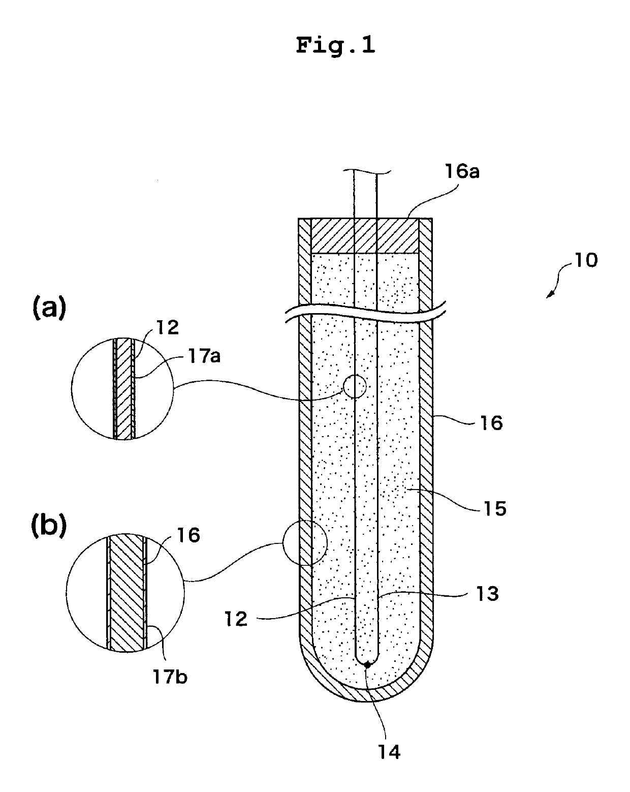
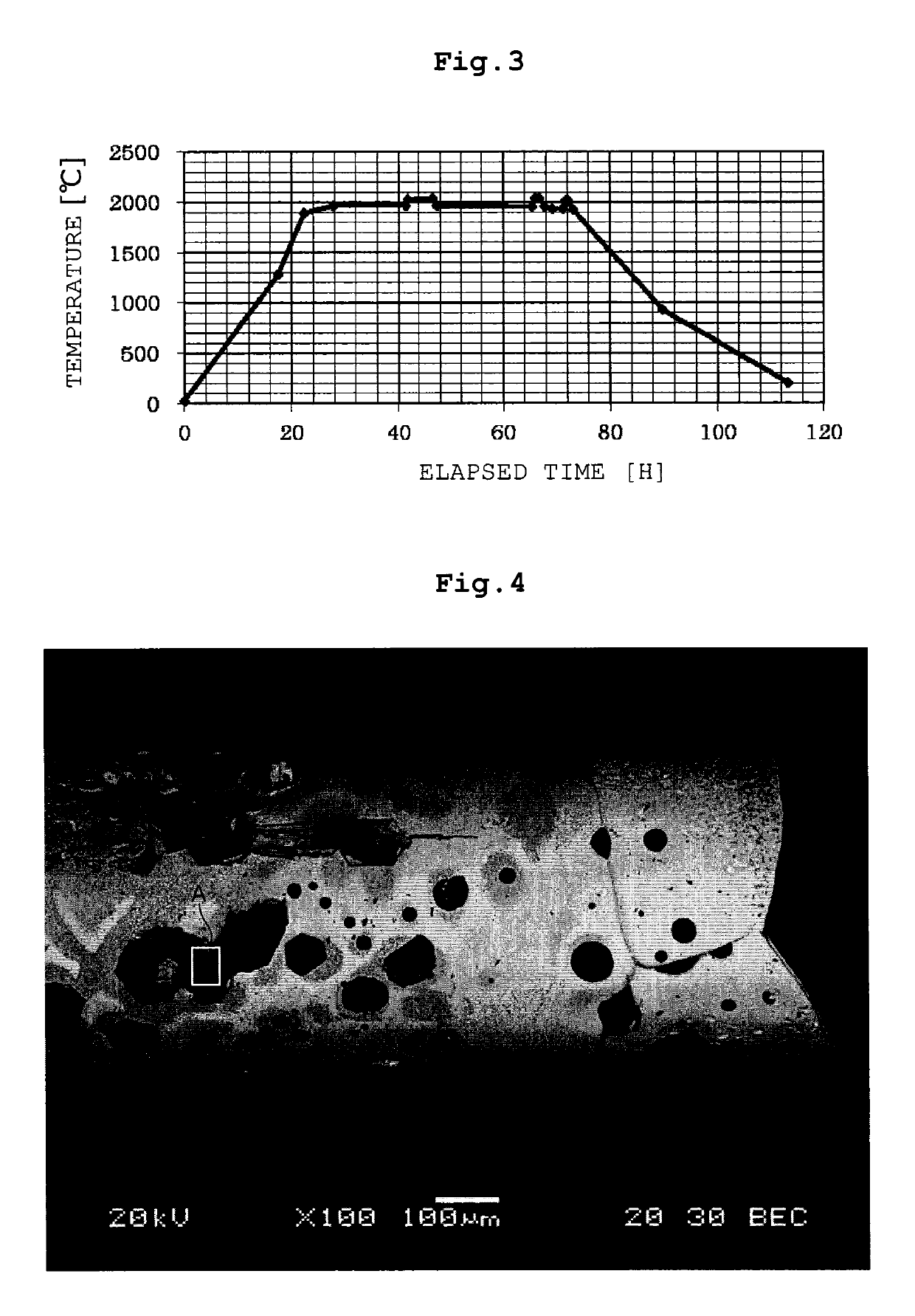
[0062]A container contained with an aluminum oxide melt was installed in an electric furnace which was maintained at a nitrogen atmosphere; an Ir wire and an Ir-40 mass % Rh wire as element wires passed through holes of an insulating tube as insulator made of a metal oxide which was composed mainly of a hafnium oxide, end portions of the Ir wire and the Ir-40 mass % Rh wire were welded to each other, thereby forming a temperature measurement junction; a thermocouple having a structure in which the element wires and the insulating tube were inserted into a protective tube made of Ir (hereinafter, described as “Ir (protective tube) / metal oxide (insulating tube) composed mainly of the hafnium oxide / Ir and Ir-40 mass % Rh (element wires)”) was vertically inserted into the electric furnace; and a temperature of the electric furnace was raised to 2000° C. and temperature measurement was performed on an area directly above the aluminum oxide melt. The protective tube had an outer diameter ...

example 2

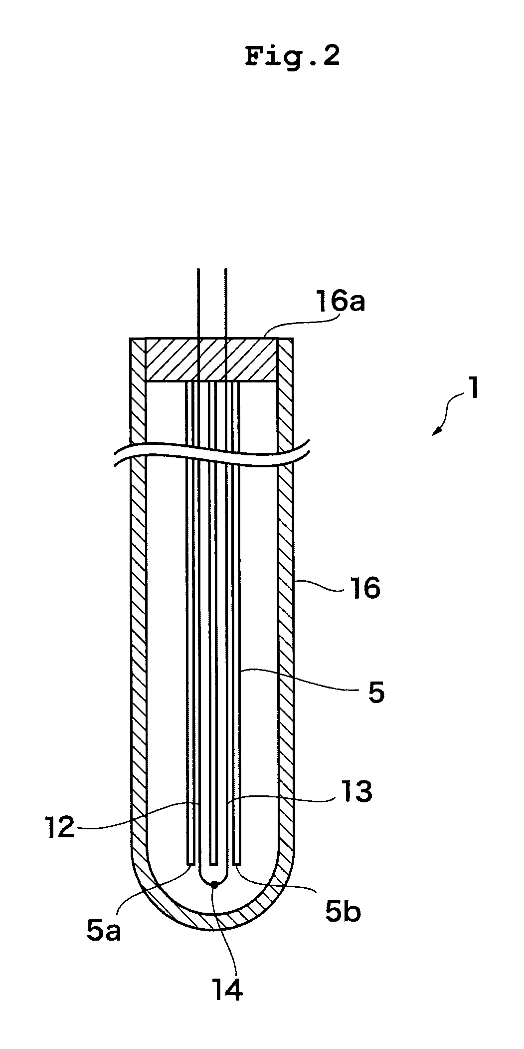
[0063]A thermocouple having a structure of Mo (protective tube) / metal oxide (insulating tube) composed mainly of the hafnium oxide / Ir and Ir-40 mass % Rh (element wires) was horizontally inserted into an electric furnace which was maintained at a nitrogen atmosphere, a temperature of the electric furnace was raised to 2000° C., and temperature measurement was performed in the inside of the furnace. The protective tube had an outer diameter of 6.4 mm and a thickness of 0.9 mm, and the inside thereof was filled with Ar to be sealed. The insulating tube had an outer diameter of 3.2 mm, and was provided with two hole-tubes having an inner diameter of 0.9 mm to insert the element wires into the insulating tube. The material of the insulating tube contains a hafnium oxide as a main component and a zirconium oxide of 0.16 mass % in terms of the amount of zirconium and is configured such that the content of each element of Al, Fe, Si, and Ti is 100 ppm or less by mass and the content of C i...

example 3

[0064]A thermocouple having a structure of W (protective tube) / metal oxide (insulating tube) composed mainly of the hafnium oxide / Ir and Ir-40 mass % Rh (element wires) was vertically inserted into an electric furnace which was maintained at a vacuum state, a temperature of the electric furnace was raised to 1900° C., and temperature measurement was performed in the inside of the furnace. The protective tube had an outer diameter of 6.2 mm and a thickness of 0.8 mm, and the inside thereof was filled with Ar to be sealed. The insulating tube had an outer diameter of 3.2 mm, and was provided with two hole-tubes having an inner diameter of 0.9 mm to insert the element wires into the insulating tube. The material of the insulating tube contains a hafnium oxide as a main component and a zirconium oxide of 0.16 mass % in terms of the amount of zirconium and is configured such that the content of each element of Al, Fe, Si, and Ti is 100 ppm or less by mass and the content of C is 10 ppm o...


PUM

PropertyMeasurementUnit
thicknessaaaaaaaaaa
thicknessaaaaaaaaaa
temperatureaaaaaaaaaa

Abstract

A thermocouple that can stably perform direct temperature measurement under a high temperature environment (1500° C. or higher but 2300° C. or lower) and a manufacturing method for the same. A thermocouple according to a first embodiment is a thermocouple including at least a protective tube and element wires, the protective tube and the element wires are insulated from one another by an insulator, and the insulator is either one or both of a powder and a compact, and is composed of at least one of a zirconium oxide, a hafnium oxide, or a composite oxide of zirconium and hafnium.

Description

BACKGROUND[0001]1. Field of the Disclosure[0002]The present disclosure relates to a thermocouple and a manufacturing method for same.[0003]2. Discussion of the Background Art[0004]In recent years, with regard to power semiconductors, glasses, and oxide single crystals of other laser elements, piezo elements, scintillator elements, or the like, performance improvement is required and a manufacturing temperature tends to increase. In addition, even with regard to an engine combustion temperature in a field of aerospace, performance improvement is required and a manufacturing temperature tends to increase. In a high temperature field of 1500° C. or higher, a radiation thermometer can be used for temperature measurement in general. In the temperature measurement using the radiation thermometer, energy of infrared light and visible light is measured in response to a temperature of an object and is converted into a temperature. For this reason, in the radiation thermometer, a temperature ...

Claims


Application Information

Patent Timeline
Patent Type & Authority Patents(United States)
IPC IPC(8): G01K7/00G01K7/04G01K7/02G01K1/12G01K1/08H01L35/02
CPCG01K1/08G01K1/12H01L35/02G01K7/04G01K7/02H10N10/80
Inventor MARUKO, TOMOHIROMIYAZAWA, TOMOAKIITO, ATSUSHISAITO, SHOJISATO, YASUHIRO
Owner FURUYA KINZOKU KK
Why Eureka
Try Eureka