
User interface for photonic tools and electromagnetic tracking guided bronchoscope

a technology of electromagnetic tracking and user interface, which is applied in the field of system for exploring the interior of objects, can solve the problems of difficult identification of the desired target site with great certainty and quick finding the way around inside the patient, and achieve the effect of facilitating “back-tracking

Active Publication Date: 2019-05-28
KONINKLJIJKE PHILIPS NV
View PDF7 Cites 1 Cited by
  • Summary
  • Abstract
  • Description
  • Claims
  • Application Information

AI Technical Summary

Benefits of technology

This patent describes a system that uses a hemoglobin or water measurement to detect malignant tissue, specifically lung tissue. The system also includes a dial element that is decorated to make it easier to read the measurement values. The system generates a measurement marker that corresponds to the position and value of the hemoglobin or water in the body. This marker is displayed in a visually appealing way and helps users decide on where to perform an action, such as biopsy. Overall, this system provides a more intuitive and accurate way to measure and detect malignant tissue in lung tissue.

Problems solved by technology

Yet, with all those tools at the disposal in modern cath labs (catheterization laboratories), quickly finding one's way around inside the patient and to identify with great certainty the desired target site still remains challenging.

Method used


Image

  • User interface for photonic tools and electromagnetic tracking guided bronchoscope
  • User interface for photonic tools and electromagnetic tracking guided bronchoscope
  • User interface for photonic tools and electromagnetic tracking guided bronchoscope

Examples


second embodiment

[0085]FIG. 6 shows a view of a GUI according to a The embodiment is in general similar to the one shown in FIGS. 4,5, but now the exploratory information on the three optical measurements B, W and S is consolidated into a single bar element 613 in a single indicator widget 612.

[0086]More particularly, color-coded dial bar 613 function as a dial and represents a super-parameter which is constructed from a suitable arithmetic combination of the optical absorbers (e.g. hemoglobin B, water W, scattering S, or others). According to one embodiment, to computation of the super-parameter is achieved as:

[0087]super⁢-⁢parameter=(hemoglobin⁢⁢saturation)×⁢water⁢(concentration)(amount⁢⁢of)⁢⁢⁢scatteringEq⁢⁢(7)

[0088]The three optical parameter B, W and S and in particular their combination as per (7) has been found to allow excellent discrimination of malignant from non-malignant tissue in particular (but not only) for lung tissue. In equation (7), “hemoglobin saturation” measures the amount of b...

third embodiment

[0091]FIG. 7 shows a view of a GUI according to a

[0092]As in the previous embodiments, in the spatial navigation window NC the EM-tracking information is displayed overlaid on previously recorded imagery 408 an / or reconstruction imagery 407.

[0093]The exploratory window PC now comprises one or more (for instance three) additional windows or panes 712a-c each including a copy of a “virtual” image as per 407 (created from the EM-tracking data and the pre-interventional reconstructions) or any other imagery of the object's interior that corresponds to the current position of the tool IT and probe PR. Each copy is overlaid, possibly multiple times, with respective 713a-c markers that represent (by color- or shape coding) the optical parameters such as blood or water content or scattering. More specifically, a respective marker dot or blob 713a-c will appear overlaid on the virtual image at a spatially correct location that corresponds to the site where the respective optical measurement ...

fourth embodiment

[0097]FIG. 8 shows a view of a GUI similar to the FIG. 7 embodiment. In this embodiment, the optical parameters or the super parameters are displayed in the navigation window NC overlaid on the navigation imagery such as the X-ray projection images in addition to the EM-tracked images. The visualization of the optical parameters against the imagery (such the x-ray image) provides a global perspective of distribution of these parameters (and hence of the distribution of blood content, scattering and water content) in the lung. The marker blobs 712a-c may also be overlaid at corresponding positions across on different cross sections of the X-ray images to obtain a 3-dimensional view. This embodiment may be used with benefit in treatment planning

[0098]As mentioned, the measurement markers 713a-c for visual recordal of the respective measurements at the various positions are shown in addition to the pointer-versus-dial bar elements widgets 412a-c or 612 of the FIG. 4 or 6 embodiments, ...


PUM


Abstract

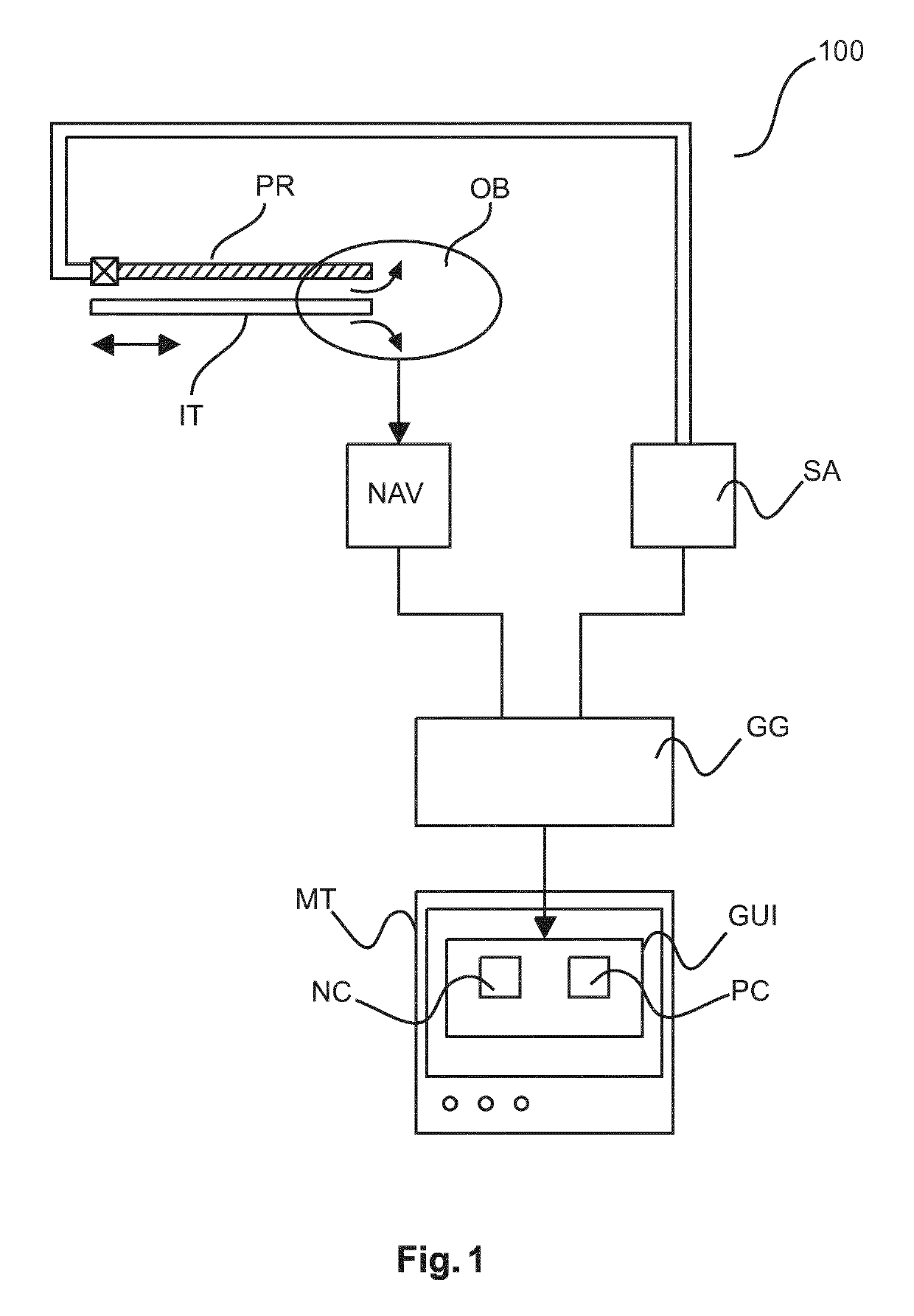
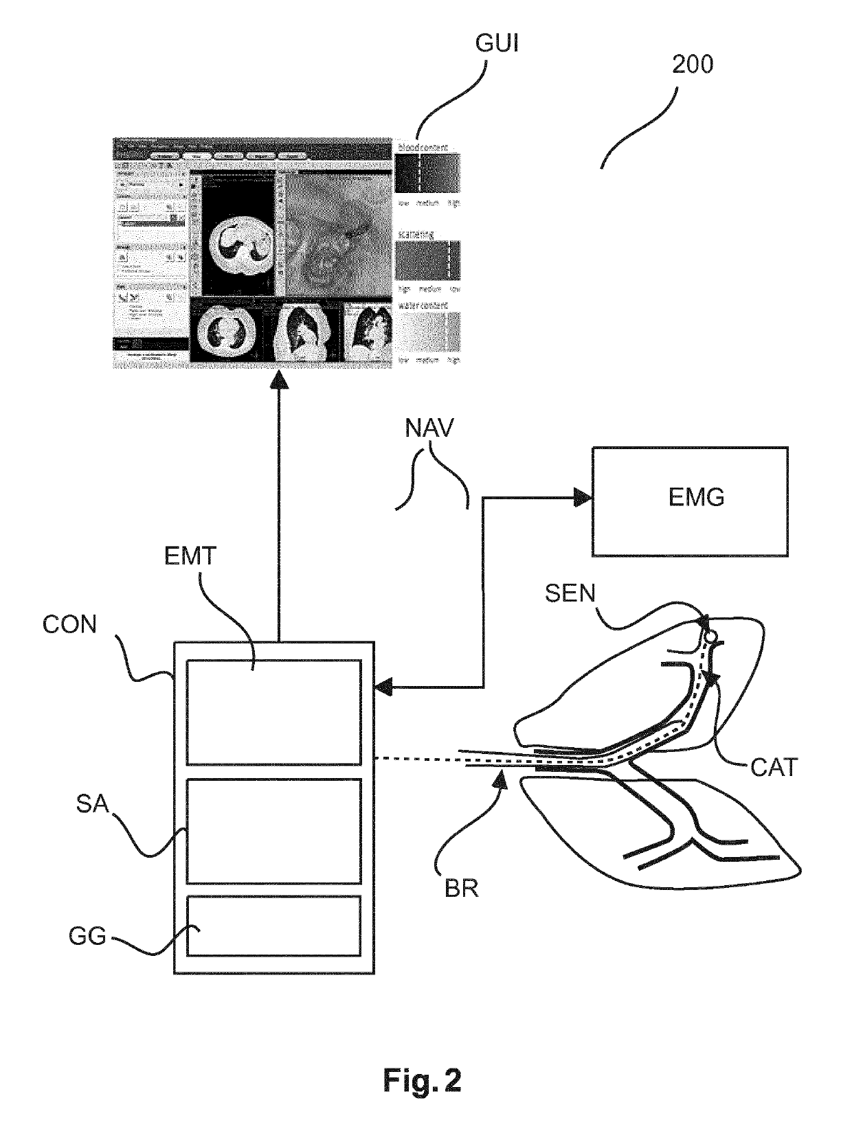
A system and method to support exploring the interior of an object. The system 100, 200 includes a graphical user interface generator (GG) to generate a graphical user interface (GUI). The graphical user interface (GUI) includes an indicator (NC) of a current position of an interventional tool (IT) inside an object (OB). There is also an exploratory indictor (PC) to indicate material composition and / or type that surrounds the tool's tip (TP) at a current position in the object (OB). The exploratory indicator (PC) includes a pointer element for a current reading against a dial element for a range of possible values.

Description

CROSS-REFERENCE TO PRIOR APPLICATIONS[0001]This application is the U.S. National Phase application under 35 U.S.C. § 371 of International Application No. PCT / EP2014 / 078102, filed on Dec. 17, 2014, which claims the benefit of U.S. Provisional Patent Application No. 61 / 918,936, filed on Dec. 20, 2013 and European Patent Application No. 14152052.8, filed on Jan. 22, 2014. These applications are hereby incorporated by reference herein.FIELD OF THE INVENTION[0002]The invention relates to a system for exploration of the interior of an object, to a method of supporting exploring the interior of an object, to a computer program element, and to a computer readable medium.BACKGROUND OF THE INVENTION[0003]Minimally invasive techniques have become the mainstay of modern medical practice. A host of sophisticated technologies and associated tools have been developed proposed in the past to help the interventionalist to make internals of the patient relatively easily accessible. Yet, with all thos...

Claims


Application Information

Patent Timeline
Patent Type & Authority Patents(United States)
IPC IPC(8): A61B5/00A61B10/02A61B5/06A61B34/00A61B90/00A61B1/267A61B34/20A61B8/08A61B17/00
CPCA61B5/0075A61B5/0084A61B5/064A61B5/742A61B10/0233A61B34/25A61B90/37A61B1/2676A61B2090/3764A61B8/0841A61B2017/00061A61B2034/2051A61B2034/2063A61B2090/365A61B2090/373A61B2090/378A61B1/00045A61B1/0004
Inventor HENDRIKS, BERNARDUS HENDRIKUS WILHELMUSBYDLON, TORRE MICHELLEVAN KEERSOP, ARNOLDUS THEODORUS MARTINUS HENDRICUSLUCASSEN, GERHARDUS WILHELMUSPARTHASARATHY, VIJAYPULLY, VISHNU VARDHANVAN DER VOORT, MARJOLEINMUELLER, MANFREDGIJSBERS, GERARDUS HENRICUS MARIA
Owner KONINKLJIJKE PHILIPS NV
Learn More