
Method and apparatus for fracturing polycrystalline silicon

a polycrystalline silicon and fracturing technology, applied in the field of polycrystalline silicon fracturing technology, can solve the problems of metal contamination, significant reduction of the lifetime of minority carriers of polycrystalline silicon, and fracture of polycrystalline silicon

Active Publication Date: 2019-06-25
XINTE ENERGY
View PDF17 Cites 0 Cited by
  • Summary
  • Abstract
  • Description
  • Claims
  • Application Information

AI Technical Summary

Benefits of technology

The present invention provides a method and apparatus for fracturing polycrystalline silicon with a uniform fracturing process, less powder generated, no metal contamination, and high-quality fractured silicon. The method uses the hydroelectric effect in a closed liquid container to generate a strong shock wave that breaks up the polycrystalline silicon. The use of pure water reduces the risk of contamination, while adjusting parameters such as the charging capacitor and main discharge gap ensures optimal fractured silicon size and reduces powder formation. The present invention achieves effective control over the fractured silicon's linear dimension and improves its quality. The apparatus is simple, secure, and easy to operate.

Problems solved by technology

In the above two methods, polycrystalline silicon is fractured due to the pressure generated by a mechanical collision between a tool for fracturing and the polycrystalline silicon to be fractured, and both methods suffer from the disadvantages as below.
1. The mechanical collision between the tool for fracturing and the polycrystalline silicon to be fractured inevitably causes metal contamination, particularly iron contamination which significantly reduces the lifetime of minority carrier of polycrystalline silicon.
2. In the mechanical fracturing process, it is inevitable to generate enormous debris and micro powder, thus lowering yield and affecting the quality of polycrystalline silicon and enterprise benefit badly.
3. The debris and micro powder generated in the fracturing process may pollute the environment and are detrimental to employee's health, besides, tiny dust is inflammable and explosive in the air, which constitutes a hidden danger.
In addition, the traditional methods for fracturing polycrystalline silicon can hardly achieve effective control over the sizes of fractured polycrystalline silicon.
However, fractured polycrystalline silicon has irregular shapes and randomly distributed sizes.

Method used


Image

  • Method and apparatus for fracturing polycrystalline silicon

Examples


embodiment 1

[0050]

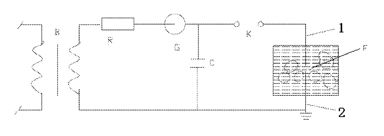
[0051]The present invention provides an apparatus for fracturing polycrystalline silicon, as shown in FIG. 1, the apparatus comprises a high-voltage transformer B, a charging resistor R, a high-voltage rectifier G, a charging capacitor C, a disconnecting switch K, a water tank F, and a first electrode 1 and a second electrode 2 which are submerged in the water, wherein the water tank F contains water, and the first electrode and the second electrode are disposed opposite to each other in the water tank.

[0052]Here, a primary winding of the high-voltage transformer B is connected to mains supply, a first terminal of a secondary winding of the high-voltage transformer is sequentially connected to the charging resistor R, the high-voltage rectifier G, the disconnecting switch K and the first electrode 1, a second terminal of the secondary winding is grounded and connected to the second electrode 2, and the charging capacitor C is connected between a common terminal of the high-vol...

embodiment 2

[0059

[0060]This embodiment provides a method for fracturing polycrystalline silicon which can be implemented by using the apparatus in Embodiment 1.

[0061]The method comprises the steps of:

[0062]step 1: filling the water tank with water taking up approximately ½˜¾ of the volume of the water tank, then placing the polycrystalline silicon in the water such that the polycrystalline silicon is submerged in the water;

[0063]step 2: applying an instant high voltage to the water tank, the intensity of the electric field generated by the instant high voltage being greater than or equal to the critical electric field intensity of the water in the water tank, wherein the specific steps are as follows:

[0064]a. The charging capacitor C is charged by the mains supply which has been converted by the high-voltage transformer B and then been rectified by the high-voltage rectifier G;

[0065]b. Once the voltage of the charging capacitor reaches the breakdown voltage of the disconnecting switch K, the di...

embodiment 3

[0073

[0074]This embodiment provides a method for fracturing polycrystalline silicon which can be implemented by using the apparatus in Embodiment 1.

[0075]The steps in the method of the embodiment are basically the same as those in Embodiment 2, except that in the embodiment, the breakdown voltage of the disconnecting switch is 80 kV, the discharge gap of the water tank F (i.e. main discharge gap) is 50 mm, and the discharge gap of the disconnecting switch (i.e. auxiliary discharge gap) varies in the range of 10˜50 mm. The resulting fracturing effect of polycrystalline silicon by using the method is illustrated in Table 3.

[0076]

TABLE 3Average particle sizeBreakdownof polycrystallineDistribution ofvoltage ofMainAuxiliarysilicon (mm)fractureddisconnectingdischargedischargeBeforeAfterpolycrystallineswitch (kV)gap (mm)gap (mm)fracturingfracturingsilicon8050101300-900-25 mm: 3%;25-50 mm: 5%;50-100 mm: 84%;above100 mm: 8%8050201300-840-25 mm: 3.5%;25-50 mm: 5%;50-100 mm: 91.5%8050301300-81...


PUM


Abstract

The present invention provides a method and an apparatus for fracturing polycrystalline silicon, and the method includes steps of placing the polycrystalline silicon in a water tank containing water; applying an instant high voltage to the water tank so that high-voltage discharge occurs in the water of the water tank to fracture the polycrystalline silicon. The method and apparatus have advantages of simple process, uniform fragments and no metal contamination.

Description

CROSS-REFERENCE TO RELATED APPLICATIONS[0001]The present application claims priority to International Application No. PCT / CN2013 / 083545 which was filed on Sep. 16, 2013 and claims priority to Chinese Patent Application No. 201210346137.3 filed Sep. 18, 2012.STATEMENT RE: FEDERALLY SPONSORED RESEARCH / DEVELOPMENT[0002]Not ApplicableFIELD OF THE INVENTION[0003]The present invention relates to the field of polycrystalline silicon fracturing technology, and particularly to a method for fracturing polycrystalline silicon and an apparatus for fracturing polycrystalline silicon.BACKGROUND OF THE INVENTION[0004]With gradual exhaustion of fossil fuel and increasingly serious environmental pollution, it is imperative to seek for a nonpolluting, renewable energy. Making the best of solar energy is of great economic and strategic significance to achieve sustainable development in low-carbon model. Polycrystalline silicon is the main raw material for fabricating solar photovoltaic cells. Fracturi...

Claims


Application Information

Patent Timeline
Patent Type & Authority Patents(United States)
IPC IPC(8): B02C19/00B02C19/18
CPCB02C19/18B02C2019/183
Inventor YIN, BOHU, GUANGJIANCHEN, XIQINGHUANG, BINLIU, GUILIN
Owner XINTE ENERGY
Learn More