
Erosion prediction method, erosion prediction system, erosion characteristics database used in this prediction, and method for constructing the same

a technology of erosion prediction and characteristics database, applied in the direction of liquid fuel engines, instruments, machines/engines, etc., can solve the problems of preventing the maintenance or reduction of the strength of the structure, the damage to the surface of the fluid machine, the damage to the pipe, etc., and the difficulty in establishing a technique for predicting the development of damag

Active Publication Date: 2019-08-20
EBARA CORP
View PDF18 Cites 0 Cited by
  • Summary
  • Abstract
  • Description
  • Claims
  • Application Information

AI Technical Summary

Benefits of technology

Enables accurate and efficient prediction of erosion in fluid machines, reducing the need for physical testing and accounting for material properties and surface changes, thereby improving prediction accuracy and reducing operational costs.

Problems solved by technology

Surfaces of a fluid machine, a pipe, or other structures in a fluid are damaged by various phenomena such as cavitation erosion or corrosion, or solid particle impact.
This prevents desired fluid performance from being maintained or reduces strength of the structures.
For such phenomena, establishing a technique of predicting development of damage is a major challenge.

Method used


Image

  • Erosion prediction method, erosion prediction system, erosion characteristics database used in this prediction, and method for constructing the same
  • Erosion prediction method, erosion prediction system, erosion characteristics database used in this prediction, and method for constructing the same
  • Erosion prediction method, erosion prediction system, erosion characteristics database used in this prediction, and method for constructing the same

Examples


Embodiment Construction

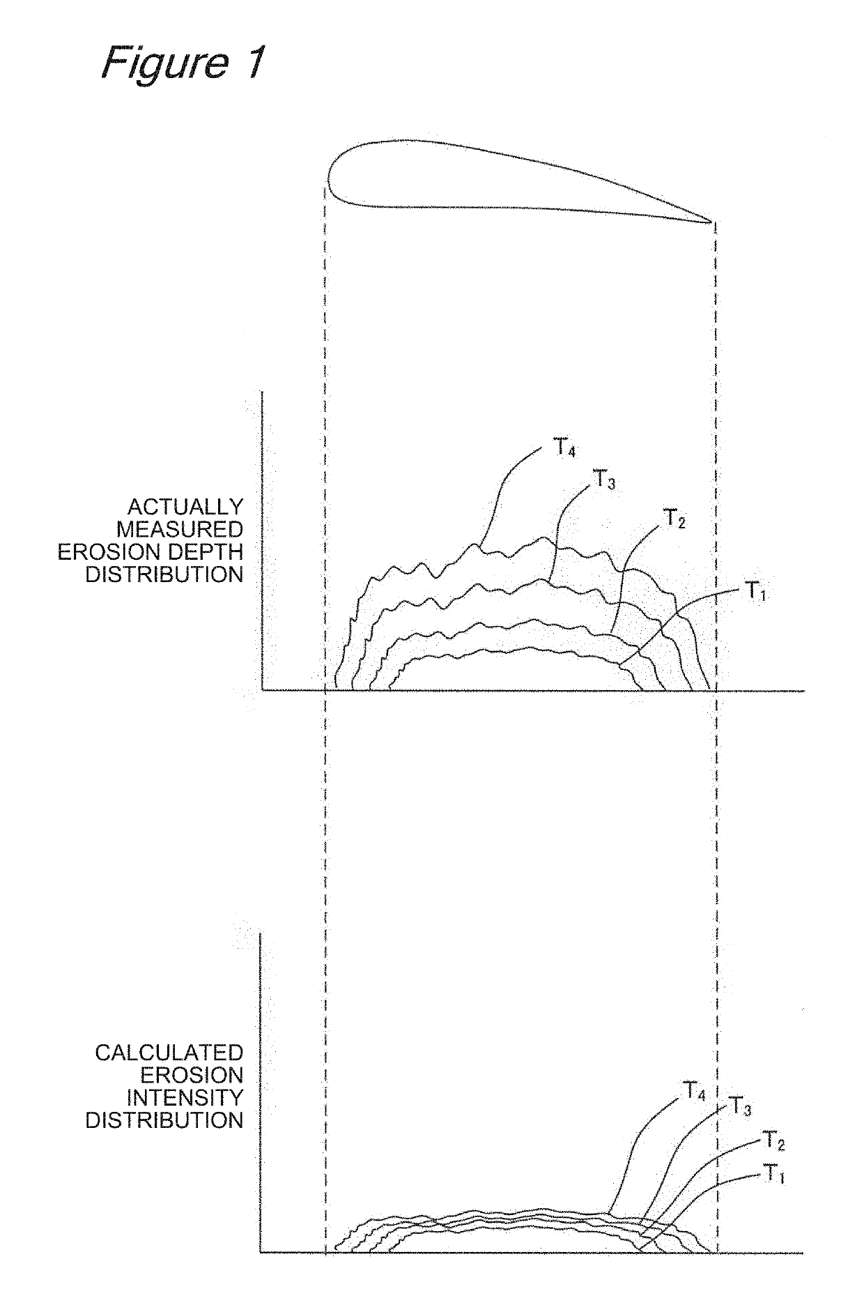
[0032]The present invention includes analyzing erosion due to cavitation using CFD as one feature. To this end, cavitation, erosion, and CFD will be first outlined.

[0033]Cavitation is a phenomenon in which when pressure in a liquid flow is lower than saturated vapor pressure, a liquid boils with extremely minute bubble nuclei in the liquid, or multiple small bubbles are formed by isolation of a dissolved gas. The cavitation causes erosion as noted by this application, or reduces a thrust force when occurring in a ship screw.

[0034]Next, erosion is a phenomenon such that collapse of bubbles generated by the cavitation described above damages a surface of a structure. The collapse of the cavitation generates an impact force of several hundred MPa or more or a microjet. Thus, if bubbles collapse near a surface of the structure, the impact force or the microjet deforms a wall surface of the structure or chips a material of the structure from the surface. Further development of erosion ca...


PUM

PropertyMeasurementUnit
timeaaaaaaaaaa
erosionaaaaaaaaaa
erosion intensityaaaaaaaaaa

Abstract

To provide an erosion characteristics database and a method for constructing the same, an erosion prediction method and an erosion prediction system using the database for predicting a widespread erosion amount of a fluid machine or the like in a short time without the need for an operation of a model machine or an actual machine.A method for predicting erosion of a fluid machine surface due to cavitation, the method including: calculating erosion intensity distribution in each area of the fluid machine surface from cavitation flow field characteristics obtained using cavitation CFD in a flow path formed by the fluid machine; determining radius distribution and center position distribution of a representative sphere and the number of shape deformations by the representative sphere for assuming an erosion surface having a porous surface property based on the erosion intensity distribution; determining a fluid machine surface to be predicted as an approximate erosion surface; and calculating a shape after deformation of the approximate erosion surface based on the radius distribution and the center position of the representative sphere and the number of shape deformations by the representative sphere.

Description

TECHNICAL FIELD[0001]The present invention relates to an erosion prediction method, an erosion prediction system, an erosion characteristics database used in this prediction, and a method for constructing the same, and more particularly to an erosion prediction method, an erosion prediction system, an erosion characteristics database used in this prediction, and a method for constructing the same for predicting in a short time, cavitation erosion produced in a fluid machine, a pipe, or other structures in a fluid.BACKGROUND ART[0002]Surfaces of a fluid machine, a pipe, or other structures in a fluid are damaged by various phenomena such as cavitation erosion or corrosion, or solid particle impact. This prevents desired fluid performance from being maintained or reduces strength of the structures. For such phenomena, establishing a technique of predicting development of damage is a major challenge. This application particularly notes prediction of cavitation erosion.[0003]Cavitation ...

Claims


Application Information

Patent Timeline
Patent Type & Authority Patents(United States)
IPC IPC(8): G01N17/00G01N3/56G06F17/50F04D15/00F04D29/66
CPCG01N17/00F04D15/0088F04D29/669G06F17/5018G01N3/567G06F2217/76F05D2260/81F05D2260/821G06F30/23G06F2119/04
Inventor NOHMI, MOTOHIKOYAKUWA, HIROSHIHAYABUSA, KEISUKENAKAMOTO, HIROAKI
Owner EBARA CORP
Learn More