
Ceramic scintillator array, method for manufacturing same, radiation detector and radiation inspection device

Active Publication Date: 2019-09-17
KK TOSHIBA +1
View PDF15 Cites 0 Cited by
  • Summary
  • Abstract
  • Description
  • Claims
  • Application Information

AI Technical Summary

Benefits of technology

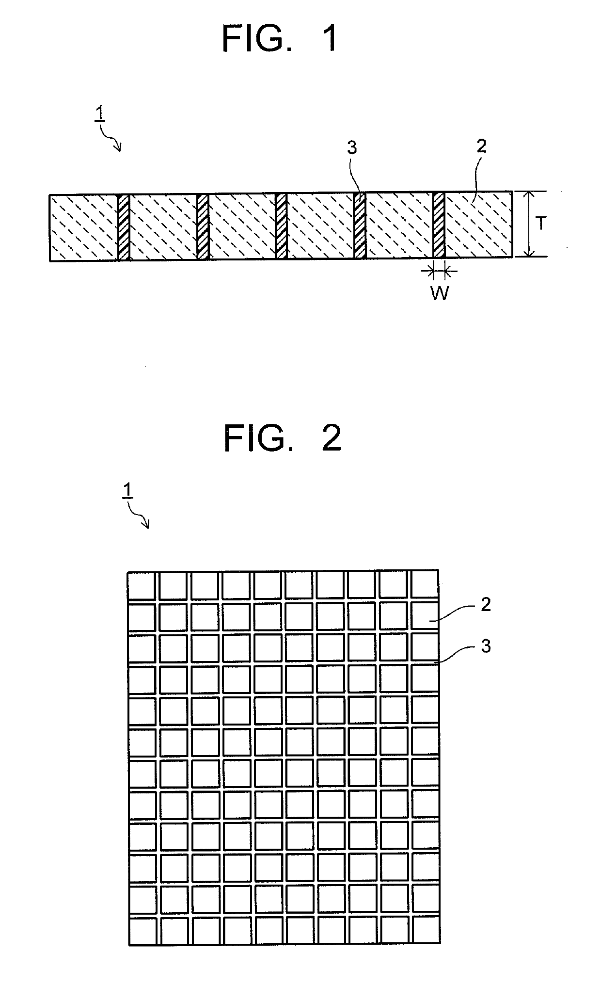
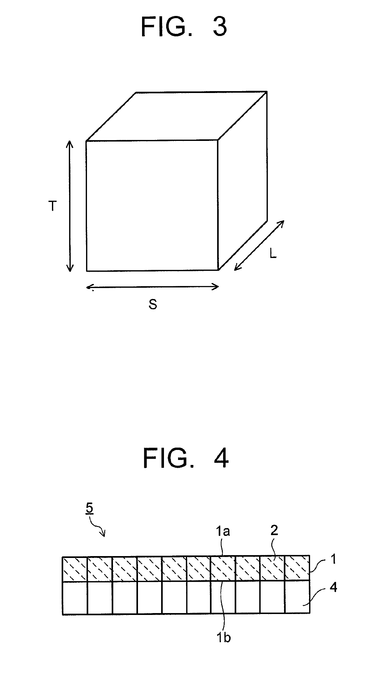
The ceramic scintillator array of this patent includes a plurality of scintillator segments made of rare earth oxysulfide phosphor, with a reflective layer in between them that integrates them. The reflective layer contains a transparent resin and reflective particles made of titanium oxide and other inorganic substances. The transparent resin has a glass transition point of 50 °C or higher and a thermal expansion coefficient of 3.5×10⁻⁵ / °C or less. The technical effect of this design is greater accuracy and resolution in detecting radiation, with reduced distortion and noise.

Problems solved by technology

These become a cause of deteriorating the resolution of the diagnostic image of the radiation detector.
For example, in the case of undergoing exposure to the X-ray for a long period such as 10 years in total, the resin contained in the reflective layer constituting the scintillator array changes in color, resulting in decreased light output.
Besides, in the case where the X-ray CT scanner is exposed to a hot and humid atmosphere, the thermal expansion rate of the resin contained in the reflective layer of the scintillator array fluctuates under the influence of the temperature and humidity, resulting in occurrence of the dimensional change of the scintillator array such as pitch shift of the segment, warpage of the scintillator array, variation in outside dimension and so on.

Method used


Image

  • Ceramic scintillator array, method for manufacturing same, radiation detector and radiation inspection device
  • Ceramic scintillator array, method for manufacturing same, radiation detector and radiation inspection device
  • Ceramic scintillator array, method for manufacturing same, radiation detector and radiation inspection device

Examples


examples 1 to 3

, Comparative Examples 1 to 2

[0046]A phosphor powder having a composition of Gd2O2S:Pr (Pr concentration=0.05 mol %) was temporarily molded by rubber pressing, and a temporarily molded body was enclosed by deaeration in a capsule made of Ta and then set in an HIP processing apparatus. Into the HIP processing apparatus, an argon gas was sealed as a pressurizing medium, and processing was carried out for 3 hours under conditions of a pressure of 147 MPa and a temperature of 1425° C. In the above manner, a sintered compact in a cylindrical shape having a diameter of about 80 mm×a height of about 120 mm was fabricated. From the sintered compact, scintillator segments each having a thickness of 0.7 mm×a width of 0.7 mm×a length of 0.8 mm were cut in a matrix form of 100 segments in the length direction and 30 segments in the width direction to fabricate the ceramic scintillator arrays according to examples and comparative examples.

[0047]The ceramic scintillator arrays according to exampl...


PUM


Abstract

A ceramic scintillator array of an embodiment includes: a plurality of scintillator segments each composed of a sintered compact of a rare earth oxysulfide phosphor; and a reflective layer interposed between the scintillator segments adjacent to each other. The reflective layer contains a transparent resin and reflective particles dispersed in the transparent resin. The reflective particles contain titanium oxide and at least one inorganic substance selected from the group consisting of alumina, zirconia, and silica. A glass transition point of the transparent resin is 50° C. or higher, and a thermal expansion coefficient of the transparent resin at a temperature higher than the glass transition point is 3.5×10⁻⁵ / ° C. or less.

Description

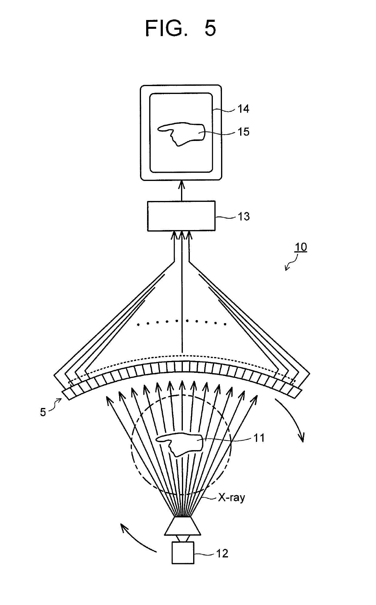
CROSS-REFERENCE TO RELATED APPLICATIONS[0001]This application is a continuation of prior International Application No. PCT / JP2016 / 083348, filed on Nov. 10, 2016 which is based upon and claims the benefit of priority from Japanese Patent Application No. 2015-222302, filed on Nov. 12, 2015; the entire contents of all of which are incorporated herein by reference.BACKGROUND OF THE INVENTION1. Field of the Invention[0002]Embodiments described herein generally relate to a ceramic scintillator array and a method for manufacturing the same, a radiation detector, and a radiation inspection device.2. Description of Related Art[0003]In fields of medical diagnosis, industrial non-destructive inspection and the like, inspection using a radiation inspection device such as an X-ray tomograph (hereinafter, described as an X-ray CT scanner) is carried out. The X-ray CT scanner is composed of an X-ray tube (X-ray source) emitting a fan beam X-ray in a fan shape and an X-ray detector including many X...

Claims


Application Information

Patent Timeline
IPC IPC(8): G01T1/20G01T7/00G01T1/202A61B6/03A61B6/00G21K4/00C09K11/77
CPCA61B6/4208A61B6/032G01T1/2023G01T1/20G01T7/00G21K4/00G01T1/2002G21K2004/06C09K11/7713
Inventor MORIMOTO, KAZUMITSUFUKUTA, YUKIHIROSAITO, AKIHISAKONDO, HIROYASU
Owner KK TOSHIBA
Learn More