
Resist composition and method for forming resist pattern

a composition and resist technology, applied in the field of resist composition and resist pattern formation, can solve the problems of scum and micro-bridges after development becoming serious problems, and defects are likely to occur in the developed resist pattern, and achieve excellent exposure stability and improved lithography properties.

Active Publication Date: 2019-10-08
TOKYO OHKA KOGYO CO LTD
View PDF44 Cites 4 Cited by
  • Summary
  • Abstract
  • Description
  • Claims
  • Application Information

AI Technical Summary

Benefits of technology

The resist composition effectively reduces defects in the developed resist pattern by enhancing lithography properties and exposure stability, improving the formation of resist patterns at the nanoscale while minimizing scum and micro bridges.

Problems solved by technology

Meanwhile, as the lithography technique further progresses and the miniaturization of the resist pattern progresses more and more, in a case of forming the resist patterns of several tens to several hundreds of nanometers, the occurrence of scum and micro bridge after development becomes a serious problem.
In addition, in the conventional resist composition in which the base resin and the acid diffusion control agent are used in combination, there is a problem of exposure stability in that defects are likely to occur in the developed resist pattern at the time of forming the resist pattern.

Method used


Image

  • Resist composition and method for forming resist pattern
  • Resist composition and method for forming resist pattern
  • Resist composition and method for forming resist pattern

Examples


examples

[0672]Hereinafter, the present invention will be more specifically described with reference to examples; however, the invention is not limited thereto.

[0673]In the present examples, a compound represented by Chemical formula (1) is denoted as a “compound (1)”, and the same is applicable to other compounds represented by other chemical formulae.

[0674]Preparation of Polymer Compound

[0675]A polymer compound (A1-1), a polymer compound (A1-2), a polymer compound (A2-1), and a polymer compound (A2-2) used in the present example were obtained by performing the radical polymerization of the following monomers providing structural units which constitute each of the aforementioned polymer compounds at a predetermined molar ratio.

[0676]

[0677]Regarding the obtained polymer compound (A1-1), polymer compound (A1-2), polymer compound (A2-1), and polymer compound (A2-2), the mass average molecular weight (Mw) and the molecular weight dispersivity (Mw / Mn) were obtained by GPC measurement (in terms o...

examples 1 to 5

, Comparative Examples 1 to 6

[0688]With respect to the each working example, the components indicated in Table 1 were mixed and dissolved to prepare a resist composition (concentration of solid contents: 3.0% by mass).

[0689]

TABLE 1(A) component(D) component(B) component(E) component(F) component(S) componentExample 1(A1)-1—(D1)-1—(B)-1(E)-1(F)-1(S)-1(S)-2[100][3.66][10][1.5][3.0][100][4000]Example 2(A1)-1—(D1)-2—(B)-1(E)-1(F)-1(S)-1(S)-2[100][4.13][10][1.5][3.0][100][4000]Example 3(A1)-1—(D1)-3—(B)-1(E)-1(F)-1(S)-1(S)-2[100][4.09][10][1.5][3.0][100][4000]Comparative(A1)-1——(D2)-1(B)-1(E)-1(F)-1(S)-1(S)-2Example 1[100][3.50][10][1.5][3.0][100][4000]Example 4(A1)-1—(D1)-4—(B)-1(E)-1(F)-1(S)-1(S)-2[100][4.16][10][1.5][3.0][100][4000]Example 5(A1)-2—(D1)-2—(B)-1(E)-1(F)-1(S)-1(S)-2[100][4.13][10][1.5][3.0][100][4000]Comparative—(A2)-1(D1)-2—(B)-1(E)-1(F)-1(S)-1(S)-2Example 2[100][4.13][10][1.5][3.0][100][4000]Comparative—(A2)-2(D1)-2—(B)-1(E)-1(F)-1(S)-1(S)-2Example 3[100][4.13][10][1.5...


PUM

PropertyMeasurementUnit
pKaaaaaaaaaaa
temperatureaaaaaaaaaa
boiling pointaaaaaaaaaa

Abstract

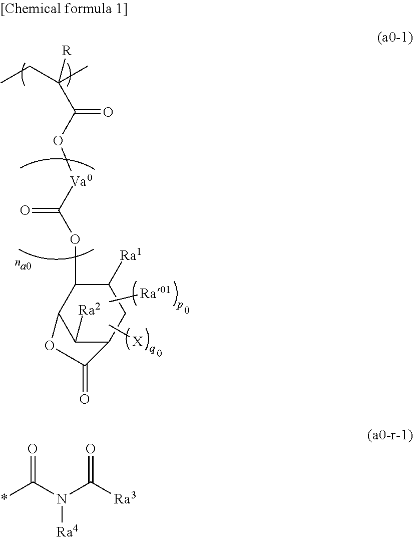
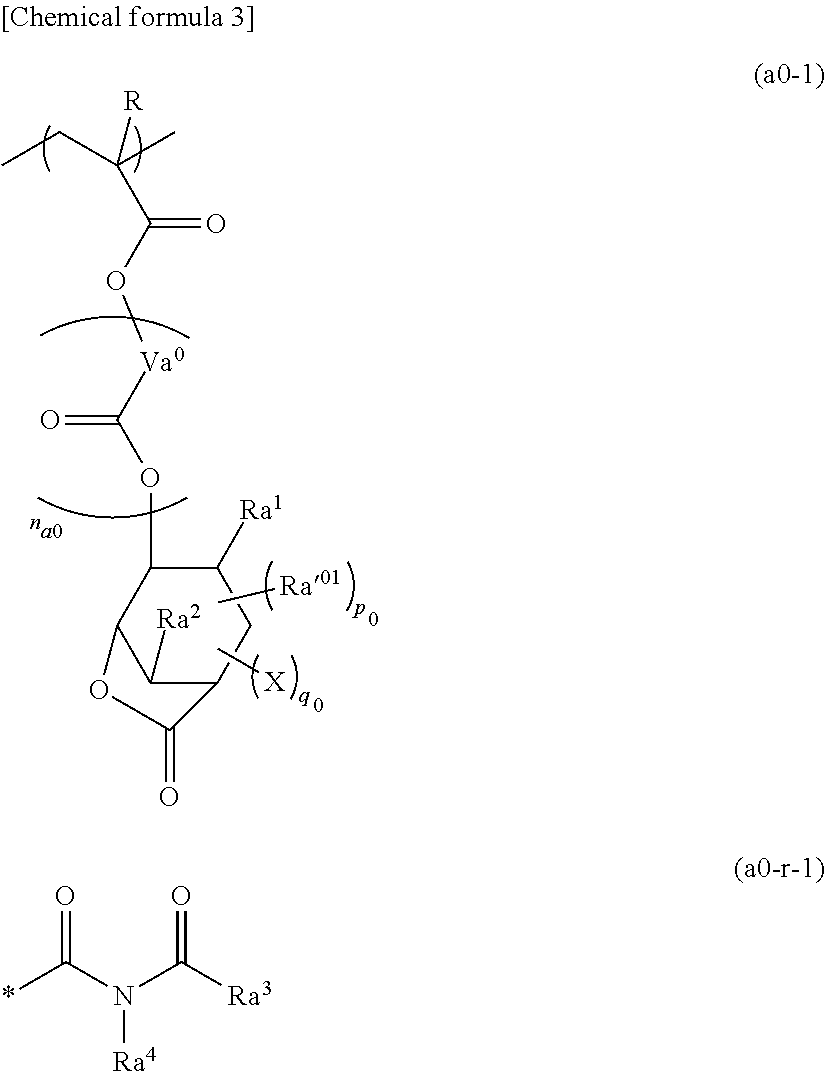
A resist composition which includes a polymer compound including a structural unit which is derived from an acrylic ester in which the hydrogen atom bonded to an α-position carbon atom may be substituted with a substituent and which has a lactone-containing cyclic group containing other electron withdrawing groups such as a cyano group at a side chain terminal, and a compound whose a conjugate acid has an acid dissociation constant (pKa) of less than 3.

Description

RELATED APPLICATIONS[0001]This application claims priority to Japanese Patent Application No. 2016-073723, filed Mar. 31, 2016, the entire content of which is hereby incorporated by reference.BACKGROUND OF THE INVENTIONField of the Invention[0002]The present invention relates to a resist composition and a method for forming a resist pattern.Background Art[0003]A lithography technique includes steps of forming a resist film composed of a resist material on a substrate, selectively exposing the resist film with light, and subjecting a developing treatment, thereby forming a resist pattern having a predetermined shape on the resist film. A resist material in which an exposed area of the resist film is dissolved in a developing solution is referred to a positive-type resist material, and a resist material in which an exposed area of the resist film is not dissolved in a developing solution is referred to a negative-type resist material.[0004]In recent years, in the manufacturing of semi...

Claims


Application Information

Patent Timeline
Patent Type & Authority Patents(United States)
IPC IPC(8): G03F7/004G03F7/16G03F7/20G03F7/32G03F7/38H01L21/027G03F7/26G03F7/09G03F7/039C07C381/12C08F224/00G03F7/038
CPCG03F7/168G03F7/0397G03F7/322G03F7/2006G03F7/26G03F7/38G03F7/091C08F224/00H01L21/0274G03F7/2041C07C381/12G03F7/16G03F7/0045G03F7/0382G03F7/004G03F7/038G03F7/039G03F7/20
Inventor NAGAMINE, TAKASHIIWASAWA, YUTA
Owner TOKYO OHKA KOGYO CO LTD
Learn More