
Growth of cubic crystalline phase structure on silicon substrates and devices comprising the cubic crystalline phase structure

a technology of cubic crystalline phase and silicon substrate, which is applied in the direction of semiconductor/solid-state device manufacturing, electrical apparatus, and semiconductor devices, etc., can solve the problems of affecting the efficiency droop effect, the green gap, and the authors' time-consuming and labor-intensive problems, and it took them around 8 days to grow such materials

Active Publication Date: 2019-10-22
STC UNM +1
View PDF30 Cites 1 Cited by
  • Summary
  • Abstract
  • Description
  • Claims
  • Application Information

AI Technical Summary

Benefits of technology

The patent text discusses the potential benefits of using cubic (c-GaN) material and its alloys in semiconductor devices. C-GaN has several advantages, including no spontaneous polarization and piezo-electric polarization, which can lead to longer wavelength band-edge emission and reduced redshift. Additionally, c-GaN has high hole mobility and can be easily cleaved, which makes it easier to fabricate devices. The text also suggests that c-GaInN structures may have better efficiency due to the Auger-recombination effect.

Problems solved by technology

Despite the impressive progress of visible light-emitting diodes (LEDs) in the nitride material system over the past two decades, two major issues are widely recognized: 1) the green gap, and 2) efficiency droop.
This is an issue since the sensitivity of the human eye peaks in the green.
This could impact the efficiency droop effects.
However, it took those authors around 8 days to grow such material.
It remains difficult to keep optimal growth conditions for such long durations, and the best material quality was believed to have been achieved only within the first 10 μm starting from the substrate.
While these are impressive results, it is generally agreed that such long growths are not compatible with cost-effective manufacturing of LEDs in high volume.
However, the total light output power from these devices is not known.
It is fair to say that the above described techniques for growing c-group-III-N compounds have involved isolated efforts that have not been suitable and accepted for device fabrication.
Many of the results showed significant levels of defects including uncontrolled spatial variations between c-GaN and h-GaN materials.
The epitaxial growth of high quality, c-group-III-N compounds at a physical scale applicable to practical device fabrication is also not well established.
This is at least partially due to various problems such as uncontrolled phase mixtures with the hexagonal phase and some issues on the selection of substrates for epitaxy related to the mismatch in crystal symmetry and lattice constant.
Generally, sapphire and SiC have been employed as substrate materials but these are incompatible with the mainstream semiconductor technology that exclusively uses Si(001) substrates.
In spite of its predominant use for microelectronics, Si has not been extensively investigated as a substrate for c-group-III-Nitrides because of these growth problems, and, for optical applications, because of the intrinsic light absorption in any remaining Si after the growth.

Method used


Image

  • Growth of cubic crystalline phase structure on silicon substrates and devices comprising the cubic crystalline phase structure
  • Growth of cubic crystalline phase structure on silicon substrates and devices comprising the cubic crystalline phase structure
  • Growth of cubic crystalline phase structure on silicon substrates and devices comprising the cubic crystalline phase structure

Examples


example 1

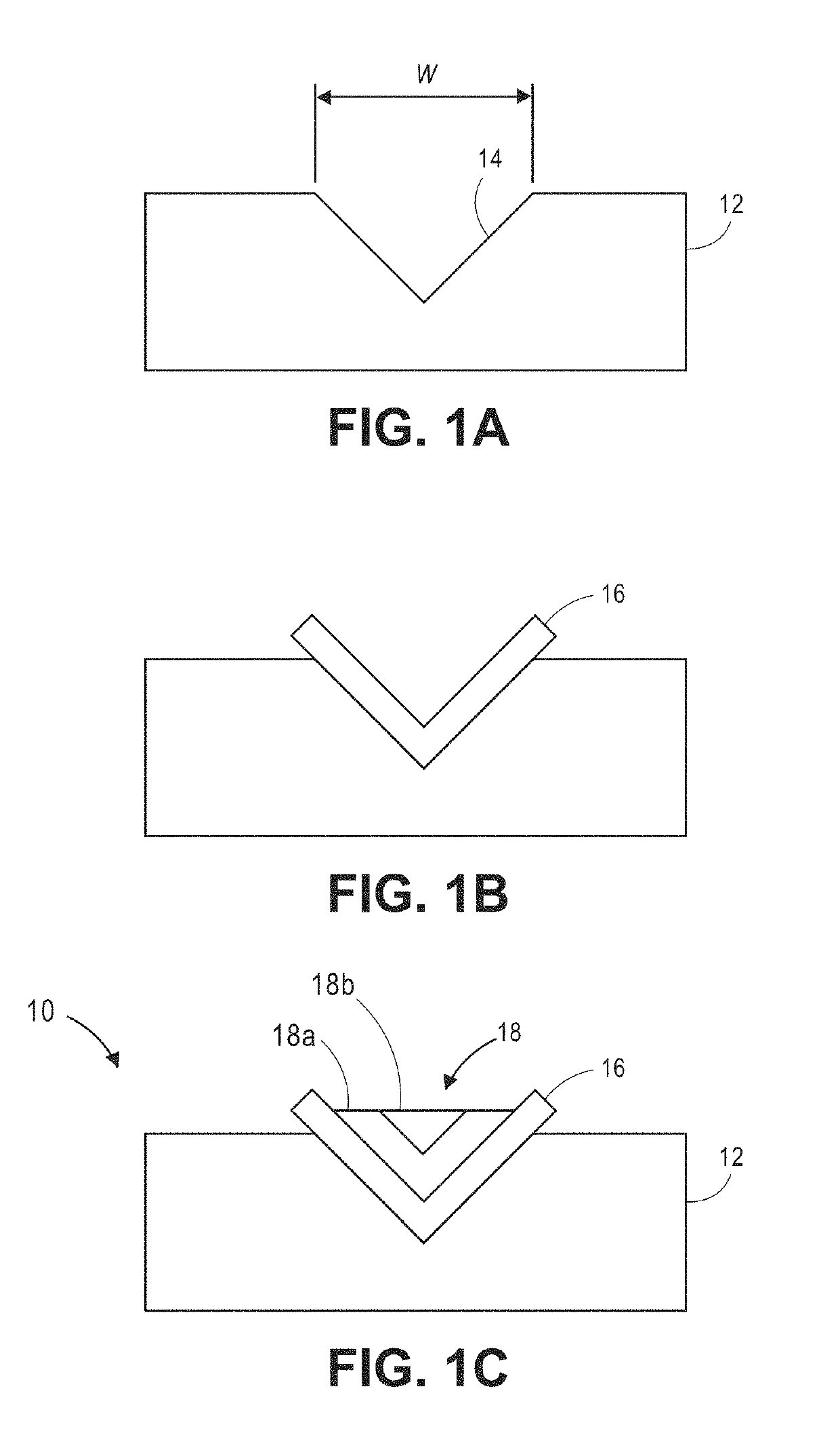
[0187]A line array of v-grooves with a period of 1.8 microns was fabricated into a Si(001) substrate by interferometric lithography with a single longitudinal transverse mode, frequency-tripled, yttrium aluminum garnet laser at a wavelength of 355-nm and anisotropic wet etching based on potassium hydroxide. The lithographic pattern was aligned so that the v-grooves were aligned approximately along the direction of the Si surface. This led to the revealing of {111} sidewalls after KOH etching. As a substrate, boron-doped Si(001) wafers with resistivity of ˜10 ohm-cm were used. An electron beam-deposited Cr film (˜200 nm) was employed as an etch mask. Each groove comprises two {111}-type facets forming a v-shape valley when viewed in cross section. The groove width was kept at ˜0.8 microns and the corresponding depth was then ˜0.6 microns.

[0188]On the v-groove-patterned substrate, a buffer comprising a thin AlN and 450 nm-thick GaN layer was grown first by MOVPE. The thin AlN was emp...

example 2

[0189]On a patterned substrate similar to that of Example 1, an additional 5 stacks of a ˜3 nm-thick InxGa1-xN well with a ˜20 nm-thick GaN spacer, and an ˜8 nm-thick GaN capping layer were consecutively grown on the 450-nm-thick GaN buffer layer. All layer thicknesses, both in Example 1 and Example 2, were calibrated on a sapphire (0001) plane as a reference. The total amount of deposition was sufficient to induce the phase transition to cubic phase by filling up each v-groove. At the same time, the deposition was controlled to avoid any coalescence between the epitaxial layers grown on adjacent grooves. Thus, most of the epitaxial layers grown on individual grooves kept the identical crystal shape even when growing beyond their initial filling of their respective groove.

example 3

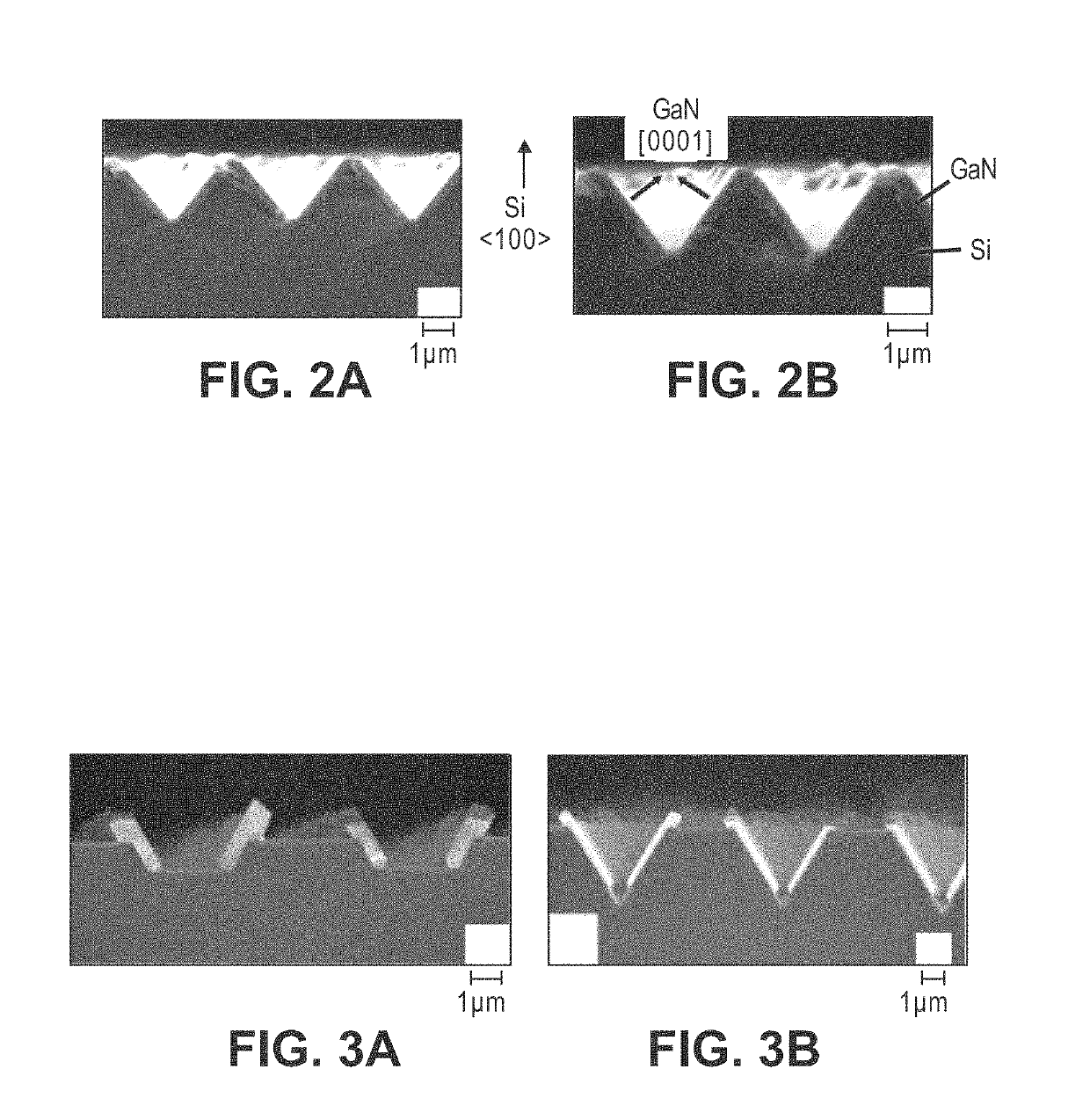
[0190]Examples of different buffer layers are shown in FIG. 2. In FIG. 2B the nucleation layer is about 25% thinner than in FIG. 2A. The resulting growth looks similar in both cases, showing good and selective nucleation normal to {111} planes. In the example of FIG. 2, no growth occurred on the flat top Si (100) surfaces between the v-grooves. The GaN on the sidewalls was smooth and continuous, but the top edges were irregularly shaped. Voids can form where the two wings from adjacent v-grooves join.


PUM


Abstract

A method of forming a semiconductor structure includes providing a substrate comprising a first material portion and a single crystal silicon layer on the first material portion. The substrate further comprises a major front surface, a major backside surface opposing the major front surface, and a plurality of grooves positioned in the major front surface. A buffer layer is deposited in one or more of the plurality of grooves. A semiconductor material is epitaxially grown over the buffer layer and in the one or more plurality of grooves, the epitaxially grown semiconductor material comprising a hexagonal crystalline phase layer and a cubic crystalline phase structure disposed over the hexagonal crystalline phase.

Description

CROSS REFERENCE TO RELATED DISCLOSURES[0001]The present application is a continuation-in-part of U.S. patent application Ser. No. 14 / 383,833, filed on Sep. 8, 2014, now U.S. Pat. No. 9,520,472, which is a 371 national stage application of PCT / US2013 / 032613, filed Mar. 15, 2015, which claims benefit under 35 U.S.C. § 119(e) from U.S. Provisional Application No. 61 / 642,680 filed on May 4, 2012, the disclosures of all of which applications are herein incorporated by reference in their entireties.GOVERNMENT INTEREST[0002]This invention was made with U.S. Government support under Grant No. EEC-0812056 from the National Science Foundation. The U.S. Government has certain rights in the invention.FIELD OF THE DISCLOSURE[0003]The present application is directed to a method of growing cubic crystalline phase structure and devices made therefrom.BACKGROUND OF THE DISCLOSURE[0004]III-N semiconductors are promising optoelectronic materials whose direct bandgap optical emission spans the ultravio...

Claims


Application Information

Patent Timeline
Patent Type & Authority Patents(United States)
IPC IPC(8): H01L29/778H01L33/00H01L21/78H01L29/04H01L33/32H01L33/04H01L33/18H01L21/02
CPCH01L33/18H01L21/0251H01L21/02502H01L21/02587H01L29/04H01L33/0079H01L21/02609H01L21/02433H01L21/0243H01L21/02381H01L21/02494H01L33/0075H01L21/0254H01L21/7806H01L21/02395H01L33/32H01L21/02458H01L33/04H01L33/007H01L33/0093
Inventor BRUECK, STEVEN R. J.LEE, SEUNG-CHANGWETZEL, CHRISTIANDURNIAK, MARK
Owner STC UNM
Learn More