Active cold air intake system

a cold air intake and cold air technology, applied in the direction of intake silencers for fuel, combustion air/fuel air treatment, electric control, etc., can solve the problems of reducing the mass flow of air to the engine, affecting the efficiency of the engine, and affecting the performance of the engine, so as to improve efficiency and performance, less pressure drop, and more cool air

Active Publication Date: 2019-11-05
SUPERTRAP IND INC
View PDF19 Cites 5 Cited by
  • Summary
  • Abstract
  • Description
  • Claims
  • Application Information

AI Technical Summary

Benefits of technology

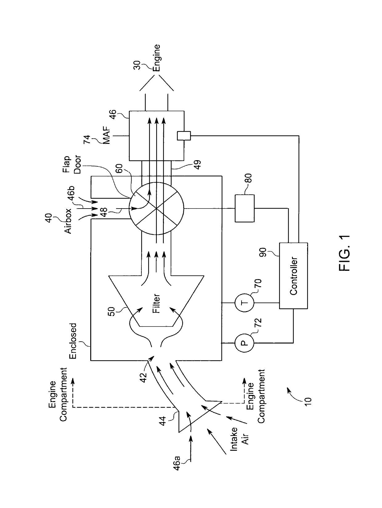
[0019]Through such operation of the airbox damper door improved efficiency and performance can be achieved, with more cool air and less pressure drop being achieved over the entire performance curve.

Problems solved by technology

While the delivery of fuel can be routinely, adequately and repeatably be delivered, delivery of air is more problematic due to its compressible flow.
For example, changes in air temperature or restrictions in airflow through the intake system can both cause detrimental performance.
As such, in addition to normal ranges and changes in atmospheric temperature, the mere increase in the temperature of the engine compartment due to the operation of the engine can diminish the mass flow of air to the engine if not accommodated.

Method used


Image

  • Active cold air intake system
  • Active cold air intake system
  • Active cold air intake system

Examples


Embodiment Construction

[0025]The best mode for carrying out the invention is presented in terms of its preferred embodiment, herein depicted within the Figures. It should be understood that the legal scope of the description is defined by the words of the claims set forth at the end of this patent and that the detailed description is to be construed as exemplary only and does not describe every possible embodiment since describing every possible embodiment would be impractical, if not impossible. Numerous alternative embodiments could be implemented, using either current technology or technology developed after the filing date of this patent, which would still fall within the scope of the claims.

[0026]It should also be understood that, unless a term is expressly defined in this patent there is no intent to limit the meaning of that term, either expressly or by implication, beyond its plain or ordinary meaning, and such term should not be interpreted to be limited in scope based on any statement made in an...


PUM


Abstract

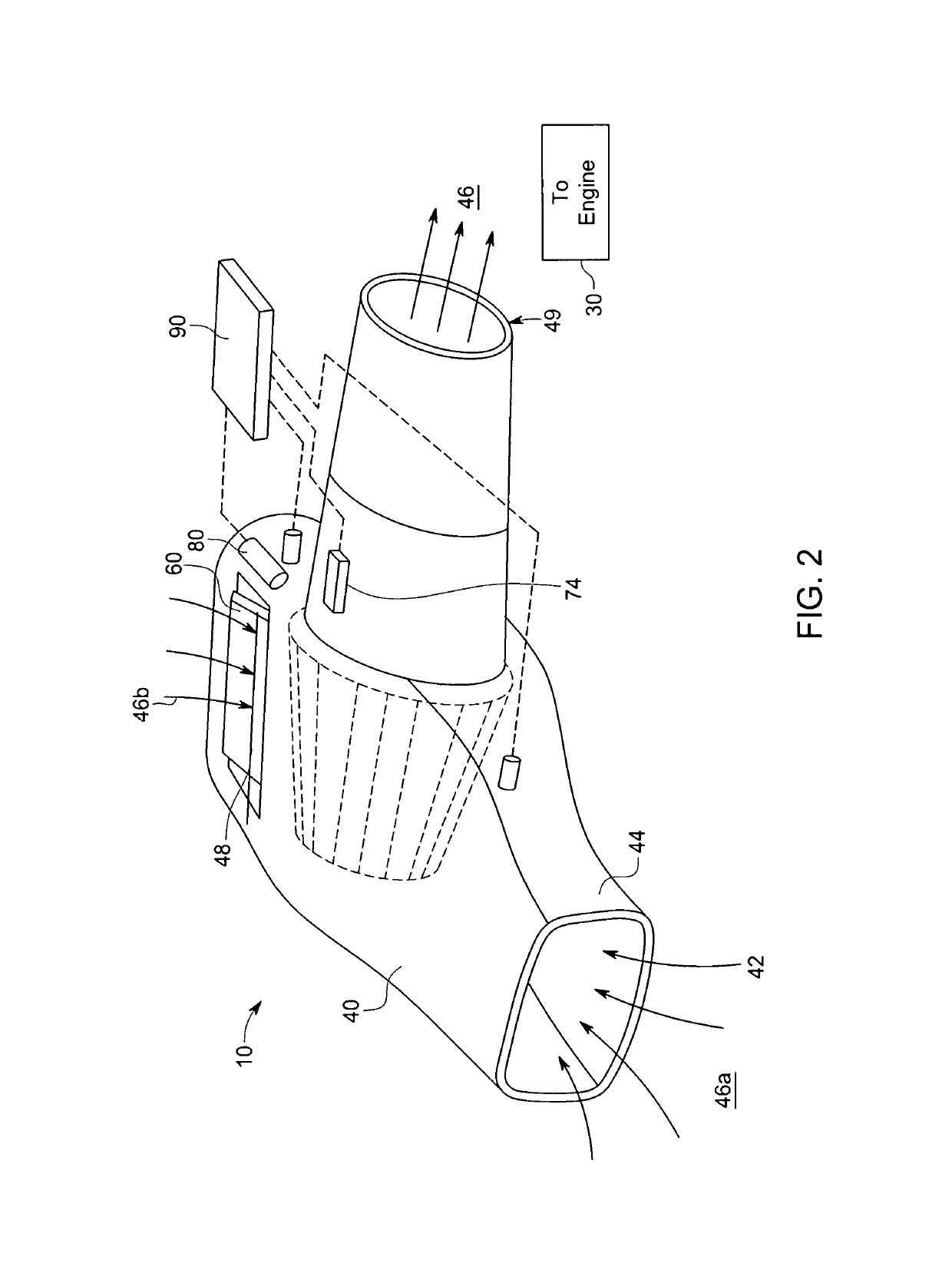
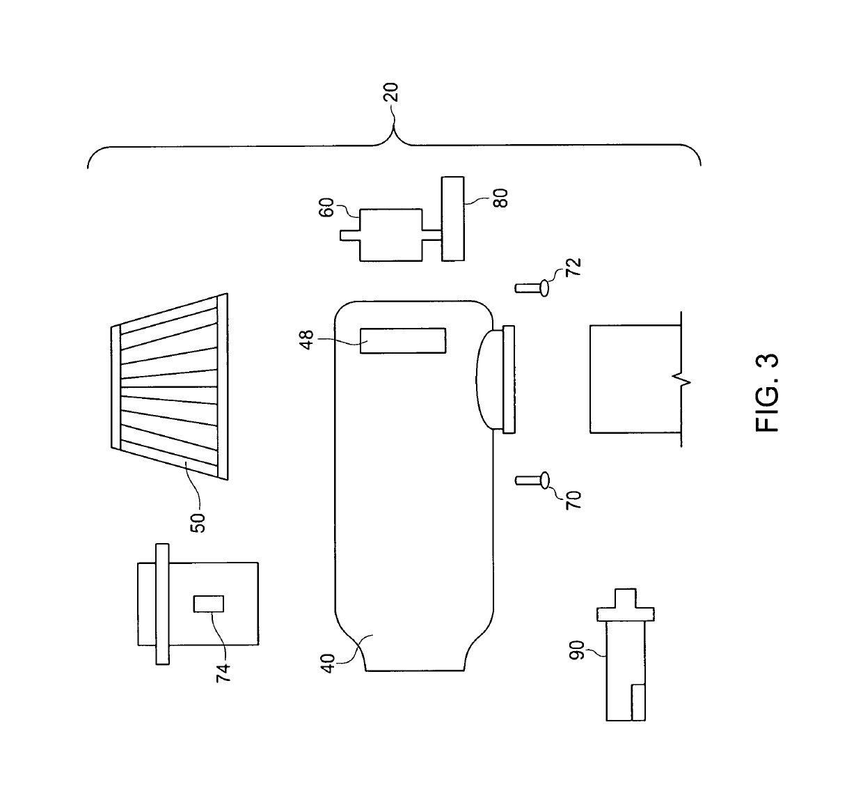
A cold air intake system is provided for actively controlling airflow based upon user input and / or demand conditions. Two air inlets are provided into a sealed air box with the secondary air intake including an air control valve for modulating intrusion of intake air. The valve has a valve seat formed the housing sidewall and a flap door valve member actively actuated via a controller. The mass air flow sensor indicates total demand. A pressure sensor and a temperature sensor provide additional input from the airbox. The controller modifies the valve position based upon pressure, temperature and mass air flow. Control is biased to increase secondary air intake when airbox pressure decreases and biased to decrease secondary air intake when airbox temperature increases. Controller biasing occurs between 30° F. to 160° F. and over pressure ranges between 0.01″ H2O to 5″ H2O.

Description

RELATED APPLICATIONS[0001]The present invention claims benefit of U.S. Provisional Application 62 / 579,323, filed on 31 Oct. 2017 and incorporated by reference as if fully rewritten herein.BACKGROUND OF THE INVENTION1. Field of the Invention[0002]The present invention relates generally to air induction systems for internal combustion engines and, more particularly, to a cold air intake system having an actively controlled airflow based upon user input and / or demand conditions.2. Description of the Related Art[0003]Air intake assemblies are provided on vehicles to deliver air to an internal combustion engine. Commonly the air intake assembly is arranged in an engine compartment and includes an air intake for collecting intake are located behind the radiator grill or in an area within a fender, an air intake duct which communicates the air to an air cleaner enclosure where it is filtered, and then to an intake manifold which direct the filtered air into the combustion chambers.[0004]In...

Claims


Application Information

Patent Timeline
Patent Type & Authority Patents(United States)
IPC IPC(8): F02M35/16F02M35/12F02M35/10F02D41/18
CPCF02M35/10386F02M35/161F02D41/182F02M35/1222F02D41/0002F02D41/18F02D2200/0406F02D2200/0414F02M35/10013Y02T10/40
Inventor WOLGAMOTT, NIKOLAS JAMES
Owner SUPERTRAP IND INC
Why Eureka
Try Eureka