Metallic surface with karstified relief, forming same, and high surface area metallic electrochemical interface

a technology of karstification and metallic surfaces, applied in the direction of metal-working apparatus, metallic material coating process, electrochemical process, etc., can solve the problems of increasing the durability of supercapacitors, reducing interfacial resistance, etc., and achieve the effect of efficient karstification

Active Publication Date: 2019-12-31
NAT RES COUNCIL OF CANADA
View PDF32 Cites 6 Cited by
  • Summary
  • Abstract
  • Description
  • Claims
  • Application Information

AI Technical Summary

Benefits of technology

[0011]Applicant made the unexpected discovery that pulsed laser ablation of thin metallic surfaces can be performed in a vacuum thin, and doing so karstifies the surface. The metallic surface may be of a thin foils, and karstification does not destroy the foil. Applicant has found the surface to have a depth (i.e. a difference between maximum depth and maximum peak height) greater than 200 nm, and more preferably 2.5 μm or more preferably 5 to 100 μm, which should be at least 5% and not more than 70% of a thickness of the karstified foil. The surface may have micron-scale or sub-micron-scale surface roughening with root mean square roughness in the range of 0.05 to 100 μm, more preferably 0.1 to 50 μm, 0.2 to 20 μm, or 0.4 to 10 μm. A resulting surface area may be 50-1000× or more that of the original surface area. A mean depth of the etching was controlled to be about 5-100 μm for a variety of examples by variation of the ablation parameters. Applicant has further found that karstified thin metallic foils can serve as high surface area current collectors used for electrodes, karstification can be beneficial for electrodes and in electrochemical cells, and metals can be efficiently karstified by vacuum laser ablation.
[0012]Coating a karstified metal surface with a metal (e.g. Ni, Ti), carbon (including graphite, pyrolytic graphite, graphene and other forms of carbon), a carbon metal composite, an alloy or mixture of metals (e.g., Ni alloys, Ti alloys, and mixtures of C with metals), metal oxides (e.g. nickel oxide; titanium dioxide; zinc oxide and indium tin oxide (ITO)), or a combination thereof, can provide a barrier coating on the foil that prevents oxidation, even when exposed to an aqueous electrolyte, for example in supercapacitor cells. The coating may be deposited by physical vapour deposition (PVD), such as: cathodic arc deposition, electron beam PVD, evaporative deposition, pulsed laser deposition or sputtering; or chemical vapour deposition (CVD), such as: atmospheric pressure CVD, low pressure CVD, ultrahigh vacuum CVD, microwave plasma assisted CVD, plasma enhanced CVD, combustion CVD, or photoinitiated CVD. Coated karstified foils are shown to not only decrease the interfacial resistance but also further increase a durability of supercapacitors with aqueous electrolytes. It is noted that advantageously the PVD process can be performed in the same vacuum chamber where the pulsed laser ablation is performed, to reduce oxidation and contamination of the sample, and expedite fabrication.

Problems solved by technology

Coated karstified foils are shown to not only decrease the interfacial resistance but also further increase a durability of supercapacitors with aqueous electrolytes.

Method used


Image

  • Metallic surface with karstified relief, forming same, and high surface area metallic electrochemical interface
  • Metallic surface with karstified relief, forming same, and high surface area metallic electrochemical interface
  • Metallic surface with karstified relief, forming same, and high surface area metallic electrochemical interface

Examples


example 1

Karstification with Solid State Q-Switched Laser

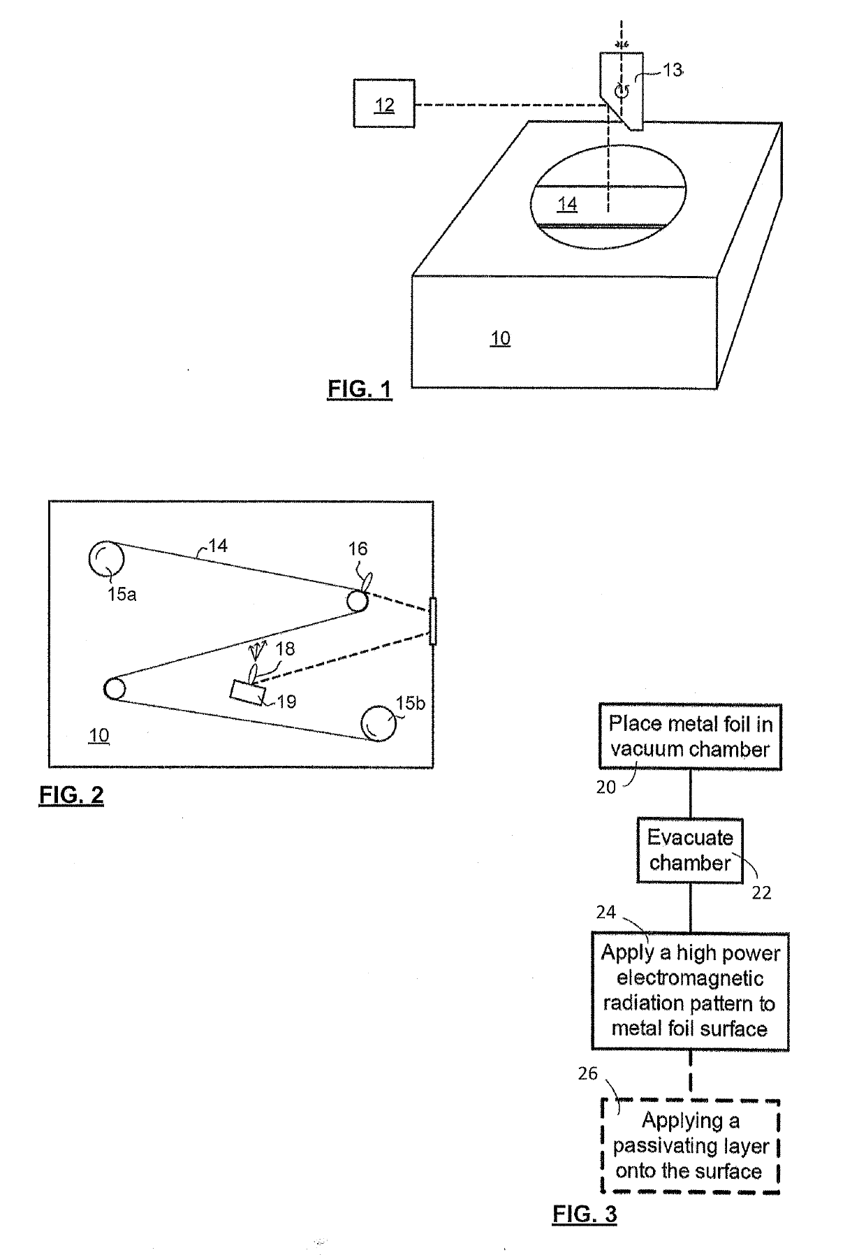
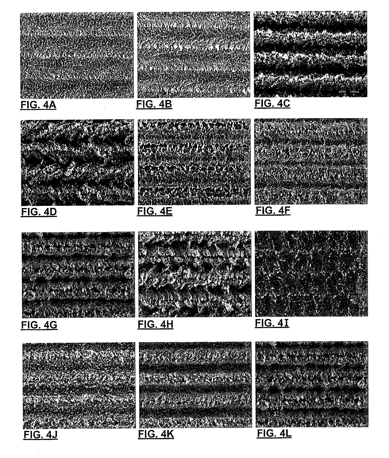
[0062]Applicant has demonstrated surface karstification by vacuum laser ablation of metallic foils. The experimental set-up for karstification included a high-vacuum stainless steel chamber with a glass cover to allow a laser beam to pass through it; a Spectra-Physics™ diode pumped solid state Q-switched laser (Model J40-BL6-106Q) operating at 1064 nm wavelength, with a power >5.0 W, energy per pulse >140 μJ, repetition rate of 1-150 kHz; an Aerotech™ X-Y-Z 3-axis motion stage to which the laser was mounted, conventional laser beam focusing optics (focusing the beam to 30 μm diameter), and sample foils (commercial grade 316 stainless steel (75 and 50 micron), aluminum foils 500, 50, 25 micron thick, and copper 25 and 50 microns) were chosen and mechanically mounted on a smooth ceramic support disc within the vacuum). The vacuum chamber was pumped down to very high vacuum level (5×10⁻⁷ Torr, although 0.5-1×10⁻⁵ Torr has been found to be...

example 2

Karstification with Excimer Laser

[0084]Applicant has also demonstrated surface karstification of metallic foils using vacuum laser ablation with an excimer laser operating using the experimental setup shown in FIG. 8. The excimer laser karstification system consisted of a KrF excimer laser (λ=248 nm, Lambda Physik, LPX-210i), beam steering and shaping optics, and a high-vacuum stainless steel chamber, equipped with a rotating plate for supporting the foils. The pulsed laser beam was focused onto the surface of an AISI 136L stainless steel, or aluminum, foil by means of a 100 cm focal length lens and three guiding mirrors. The laser beam was scanned over the radius of the rotating metallic foils using a preselected program and the plate was rotated at 35 rev / min. Scanning was performed using a programmable kinematic mount for the last mirror of the optical train. The laser beam spot size at the target surface was approximately 4 mm2. The on-target laser beam fluence was adjusted to a...


PUM

PropertyMeasurementUnit
roughnessaaaaaaaaaa
thicknessaaaaaaaaaa
thicknessaaaaaaaaaa

Abstract

A metal foil with a karstified topography having a surface morphology in which a maximum peak height minus a maximum profile depth is greater than 0.5 μm and extends into the surface at least 5% of the foil thickness, a root mean square roughness is at least about 0.2 μm measured in a direction of greatest roughness, and an oxygen abundance is less than 5 atomic %. The foil may be composed of aluminum, titanium, nickel, copper, or stainless steel, or an alloy of any thereof, and may have a coating composed of nickel, nickel alloy, titanium, titanium alloy, nickel oxide, titanium dioxide, zinc oxide, indium tin oxide, or carbon, or a mixture or composite of any thereof. The foil may form part of a metal electrode, current collector, or electrochemical interface. Further described is a method for producing the foil by laser ablation in a vacuum.

Description

FIELD OF THE INVENTION[0001]The present invention relates in general to application of surface morphology to metallic foils, and in particular to a technique for producing karstified relief on metallic foils, such as foils of Al, Cu, or Stainless Steel for use in current collectors, electrodes and like electrochemical interfaces, such as those used in energy storage devices such as batteries, and supercapacitors.BACKGROUND OF THE INVENTION[0002]One of the strategies to increase the power density of supercapacitors is the optimization of the interface between active material and current collectors, electrodes, or electrochemical interfaces, which are referred to herein as electrode surfaces. Herein a current collector is a thin film that is electrically connected to a larger conductive body to promote interaction between the conductive body and an active material, the conductive body and current collector forming an electrode. An electrode or electrochemical interface may be karstifi...

Claims


Application Information

Patent Timeline
Patent Type & Authority Patents(United States)
IPC IPC(8): B21D39/00H01G11/70B23K26/00H01G11/24B23K26/352C23C14/08H01G11/26C23C14/02H01M4/80H01M4/78H01M4/66H01M4/1391H01M4/136H01M4/04B23K26/08B23K26/0622B23K26/12C23C14/06C23C14/28H01G11/32H01G11/46B23K101/36B23K101/38B23K103/04B23K103/10B23K103/12B23K103/14B23K103/18
CPCH01G11/26B23K26/0823H01M4/1391H01M4/78C23C14/028C23C14/28H01M4/80H01M4/0423H01G11/24B23K26/0846H01G11/70H01M4/661B23K26/352B23K26/0624B23K26/1224C23C14/0605B23K26/355B23K26/0006H01M4/0404H01M4/136B23K26/127B23K26/0876B23K26/3568C23C14/08H01M4/0426Y02E60/13B23K2103/26H01G11/46B23K2101/36B23K2103/14B23K2101/38B23K2103/05B23K2103/12Y10T428/12431Y10T428/12472B23K2103/10H01G11/32Y02E60/10
Inventor YANG, DONGFANG
Owner NAT RES COUNCIL OF CANADA
Why Eureka
Try Eureka