Carburization device and carburization method

a carburizing device and carburizing technology, applied in the direction of heat treatment equipment, lighting and heating equipment, furnaces, etc., can solve the problems of reducing fatigue strength, reducing compressive stress, and occurrence of decarburization (ferrite decarburization or partial decarburization) near the surface of the spring to some extent, so as to achieve safe and efficient use of less equipment.

Active Publication Date: 2020-03-10
NAT UNIV CORP YOKOHAMA NAT UNIV +1
View PDF19 Cites 2 Cited by
  • Summary
  • Abstract
  • Description
  • Claims
  • Application Information

AI Technical Summary

Benefits of technology

[0009]Accordingly, an object of the present invention is to provide a carburization device and a carburization method capable of performing the carburization treatment, which is carried out in a manufacturing process of a steel product such as a spring member, safely and efficiently with less items of equipment.
[0012]According to the embodiment, a large-scale conversion furnace or a dedicated carburizing furnace for producing carburizing gas becomes unnecessary, and the carburization treatment, which is carried out in a manufacturing process of a steel product such as a spring manufacturing process, can be performed safely and efficiently with less items of equipment.

Problems solved by technology

Accordingly, occurrence of decarburization (ferrite decarburization or partial decarburization) near a surface of the spring to some extent is unavoidable.
When the spring is decarburized, the quenching hardness or the hardness after tempering is lowered, which becomes a factor of reducing the yield stress, and furthermore, reducing the fatigue strength.
However, with the shot peening, it is not possible to produce compressive stress greater than the yield stress of a material to be treated (for example, a suspension spring).
However, these existing carburizing methods require a gas conversion furnace or a dedicated carburizing furnace.
For this reason, not only is there a case where additionally installing such furnaces in the existing facilities where a spring manufacturing process is performed is difficult, but a large expense is also necessary.
Under the circumstances, a carburization treatment cannot be performed for a steel product manufactured by hot working which is continuously processed in a heat treatment furnace.
For this reason, with the existing carburization technology, it is difficult to perform the carburization treatment by using the heat treatment furnace of an open system if the material is one which moves in a continuous manufacturing line of steel products.
In addition, since explosive carburizing gas such as propane is used, extreme caution must be taken when handling the gas.

Method used


Image

  • Carburization device and carburization method
  • Carburization device and carburization method
  • Carburization device and carburization method

Examples


first embodiment

[0032]A carburization device will be described with reference to FIGS. 1 to 4.

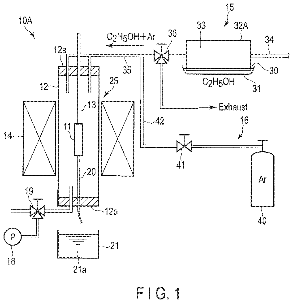
[0033]FIG. 1 schematically shows the structure of a carburization device 10A implemented at a site equivalent to a laboratory. The carburization device 10A includes a container 12 which accommodates a material 11 made of steel, a holder 13 which holds the material 11 within the container 12, an infrared-ray converging-type heater 14 which heats the material 11, an alcohol vapor supply system 15 which is an example of an organic compound supply system, an inert gas supply system 16, an exhaust pump 18, a switching valve 19, a temperature sensor (a thermocouple) 20 which detects a temperature of the material 11, a cooling tank 21 which is to be used in quenching the material 11, etc. Cold water 21a is accommodated in the cooling tank 21.

[0034]The container 12 is constituted of a quartz tube, for example, and keeps the inside of the container 12 airtight by an upper lid 12a and a bottom lid 12b which is open...

second embodiment

[0046]A carburization device will be described with reference to FIGS. 5 and 6.

[0047]FIG. 5 schematically shows a carburization device 10B which performs carburization at a site equivalent to a factory in a spring manufacturing process. The carburization device 10B comprises a heating furnace 50, a transfer mechanism 55, an alcohol vapor supply system 56, an alcohol vapor spraying portion 57, a quenching tank 58 as the quenching means, etc. The heating furnace 50 functions as a heat treatment furnace which heats a material 11 made of spring steel. The transfer mechanism 55 moves a plurality of materials 11 from an inlet portion 51 of the heating furnace 50 toward an outlet portion 52 of the same. A quenching liquid such as water or oil is accommodated in the quenching tank 58.

[0048]The heating furnace 50 forms a flame by burning inflammable gas such as city gas. By this flame, the material 11 is heated to a temperature (for example, 980° C.) at which the quenching can be performed....


PUM

PropertyMeasurementUnit
lengthaaaaaaaaaa
diameteraaaaaaaaaa
timeaaaaaaaaaa

Abstract

A carburization device includes a heating furnace which heats a material, a transfer mechanism, an alcohol vapor generator, an alcohol vapor spraying portion, a quenching tank, and an exhaust heat intake tube. The transfer mechanism moves a plurality of materials. The alcohol vapor generator uses part of heat generated by the heating furnace as a heat source. As the alcohol vapor spraying portion repeats a vapor spraying step and a diffusion step a plurality of times in the heating furnace. In the vapor spraying step, by spraying alcohol vapor on the material which moves inside the heating furnace, carbon in the alcohol is adsorbed to the material. In the diffusion step, an interval for diffusing the carbon adsorbed to the material is taken.

Description

CROSS-REFERENCE TO RELATED APPLICATIONS[0001]This application is a Continuation Application of PCT Application No. PCT / JP2016 / 064183, filed May 12, 2016 and based upon and claiming the benefit of priority from prior Japanese Patent Application No. 2015-101781, filed May 19, 2015, the entire contents of all of which are incorporated herein by reference.BACKGROUND OF THE INVENTION1. Field of the Invention[0002]The present invention relates to a carburization device and a carburization method for carburizing a steel product such as a spring member and various machine elements.2. Description of the Related Art[0003]In order to achieve the weight reduction of a vehicle such as a car and to improve fuel efficiency, reducing the weight of components which constitute the vehicle has been desired. Among the components which constitute the vehicle, a suspension spring is relatively heavy in weight as a unit, and is also an important component which supports the weight of the vehicle. Accordin...

Claims


Application Information

Patent Timeline
Patent Type & Authority Patents(United States)
IPC IPC(8): C23C8/22C21D1/06C23C8/80F27B9/04F27D17/00F27B9/30F27B9/40C23C8/20C21D9/02
CPCF27B9/045F27B9/3005C23C8/80F27D17/004F27B9/40C21D9/02C23C8/22C21D1/06C23C8/20C21D1/76C21D9/0056
Inventor NAKAO, WATARUTANGE, AKIRATANGO, KOICHIKAI, MORIMICHI
Owner NAT UNIV CORP YOKOHAMA NAT UNIV
Why Eureka
Try Eureka