
Method and apparatus for tracing sewer connections with RFID PIT tags

Active Publication Date: 2020-05-05
CRUZ JASON
View PDF22 Cites 3 Cited by
  • Summary
  • Abstract
  • Description
  • Claims
  • Application Information

AI Technical Summary

Benefits of technology

The patent text describes a method for testing and tracing connections in a plumbing system using RFID PIT tags with protective outer coverings. The RFID PIT tags are released at one point in the system and detected at another point using an RFID reader and antenna system. The use of RFID PIT tags offers advantages over other methods such as dye testing and camera inspection, including lower costs, no need for constant oversight, and greater certainty in test conclusions. The protective outer coverings can be made from paraffin wax or other materials to suit different testing situations.

Problems solved by technology

Unfortunately defects and improper connections may be present in and among plumbing systems, sewer lateral pipes and sewer systems.
One type of defect is known as “cross-connection”, an undesirable condition in which there is a leak or hydraulic connection between components of the sanitary and storm sewer systems.
For example, one or more sanitary sewer lateral pipes may be improperly connected to a storm sewer.
Alternatively, storm sewer lateral pipes or other stormwater drainage infrastructure may be improperly connected to a sanitary sewer system.
Sanitary sewage disposed in a home with a cross-connected plumbing system may not be conveyed to a wastewater treatment plant and may contaminate a storm sewer system that is not designed for sanitary sewage.
Contaminated stormwater and sanitary sewage may then be released into the environment, causing pollution of surface waters or groundwater aquifers.
Sewer lateral pipe and sewer system defects can thus cause or contribute to bacterial contamination and impairment of water supply uses of surface water and groundwater and may also impair recreational uses of surface waters.
The improper connection of storm sewer lateral pipes or other stormwater drainage infrastructure to a sanitary sewer system is also problematic.
As stormwater flow takes up space within the sanitary sewer system, the capacity of the sanitary sewer system to convey sanitary waste decreases, potentially resulting in basement backups or sanitary sewer overflows.
Even if the additional stormwater flow can be conveyed without overflowing, treatment costs for wastewater treatment plants can increase, as the facility will have to treat a greater amount of flow than if only sanitary waste is collected and conveyed to the treatment works.
The dye testing process is labor-intensive as it usually requires at least two persons.
This feature of the dye testing method is disadvantageous, making it a time-consuming affair to sequentially test multiple fixtures within a property and impractical to conduct tests of multiple properties or locations within the same sewer system network simultaneously.
Moving the work zone and opening additional manholes or other access points can be time consuming and labor-intensive, as manhole covers are often found to be jammed with paving materials and debris.
Workers may incur the dangers of using striking, prying and lifting tools to open additional manholes.
Ladders, wet conditions and sewer gases such as hydrogen sulfide and methane are also potential hazards for observers that may enter the confined space of a manhole to make observations for the presence of dye.
Another safety disadvantage of dye testing is that suitable observation points such as manholes are often located within roads or other areas subject to vehicle or foot traffic.
Furthermore, at any time when a person is required to occupy an observation position in a road or other location where vehicles are operated, there exists the danger of the worker being struck by a vehicle.
Closing lanes or entire roads to safely accommodate dye testing observers can cause inconvenience for motorists and may impede emergency vehicles.
Environmental conditions such as bright daylight can cause large differences in contrast between the ambient outdoor environment and the sewer system being tested, which is typically much darker.
Flashlights are often used to illuminate the sewer observation point, but on bright days it may be difficult to see the dye unless a relatively large quantity of dye is used.
Although dyes used for sewer system testing are typically non-toxic, dyes are expensive and have other undesirable characteristics such as the potential for staining surfaces and the unintended or unanticipated observation of dye at other non-testing locations.
Cameras can be impeded by pipe geometry, various types of pipe defects, or obstructions caused by tree roots or other debris.
These advanced technologies tend to require specialized equipment and skilled operators and are currently prohibitively expensive for use in plumbing system and sewer lateral pipe investigations.
Disadvantages of Current Sewer Inspection Method
As the need to inspect and test sewer lateral connections grows with tightening environmental regulations and deterioration of older sewer systems, owners and operators of sewer systems may find themselves needing to test a large number of sewer connections over a large geographical service area.
It is possible to use different colors of dye to marginally increase the number of fixtures that can be tested concurrently, but this approach is limited by the number of colors of available dye that can be discriminated by an observer and is still subject to the disadvantages described above in terms of sequential testing.
Neither dye testing nor camera inspection can yield the type of test results that can be quickly and readily integrated into an automated information technology workflow.
From the preceding information, it is clear that there are significant disadvantages to existing methods for testing plumbing systems, sewer lateral pipes and sewer systems under some test conditions and for certain testing objectives.

Method used


Image

  • Method and apparatus for tracing sewer connections with RFID PIT tags
  • Method and apparatus for tracing sewer connections with RFID PIT tags
  • Method and apparatus for tracing sewer connections with RFID PIT tags

Examples


Embodiment Construction

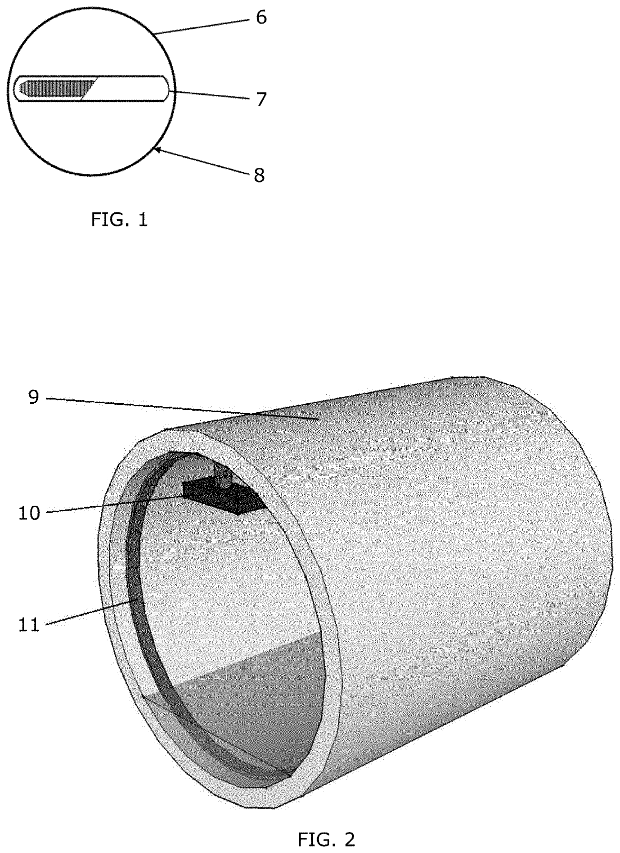
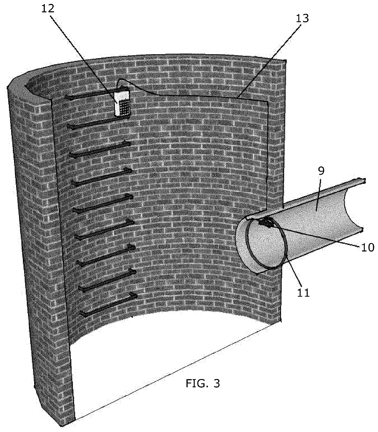
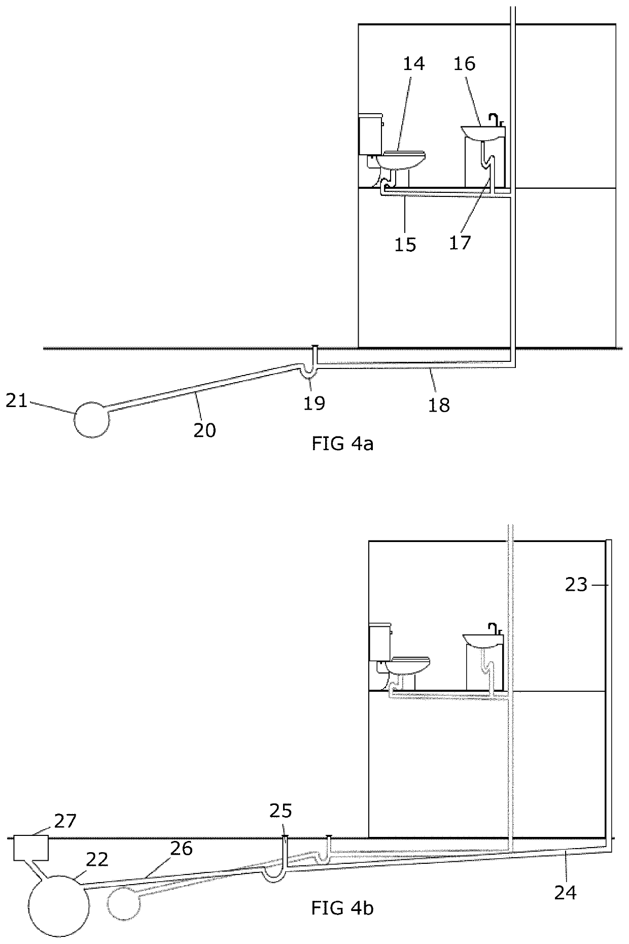
[0022]In one or more aspects, the embodiments provide effective, low cost methods for testing and tracing connections within a plumbing system, sewer lateral pipe, sanitary or storm sewer system with RFID PIT tags. Waterproof antenna designs commonly used for fish hatcheries and fish monitoring are commercially available and readily adaptable to sewer monitoring conditions. Similarly, weatherproof computerized RFID PIT tag reader systems are readily available and suitable for deployments within manholes or other access points within a sewer system. Evidence of a hydraulic connection between two points in a plumbing system, sewer lateral pipe, sanitary or storm sewer system can be established by releasing, or introducing an RFID PIT tag at one point within a plumbing system, sewer lateral pipe, or sewer system and detecting the presence of the RFID PIT tag by interrogating and reading the tag at a second point within a sewer lateral pipe, sanitary or storm sewer system with an RFID P...


PUM


Abstract

A method and apparatus for tracing sewer connections with RFID PIT tags consists of using at least one radio frequency identification (RFID) passive integrated transponder (PIT) tag embedded within a protective outer covering, and at least one RFID reader and antenna system to trace the flow of a fluid within a plumbing system, sewer lateral pipe, sanitary or storm sewer system. The RFID PIT tag and protective outer covering are introduced in one point within the plumbing system, sewer lateral pipe, sanitary or storm sewer system, such as by flushing a toilet. Subsequent collection, or detection of the RFID PIT tag at another location within a sewer lateral pipe, sanitary or storm sewer system is used to establish the presence of a hydraulic connection between the introduction and collection or detection points. The method is useful to identify whether a plumbing system or sewer lateral pipe is properly connected to a sewer system without the need to actively observe the presence of a visual tracing aid such as dye.

Description

CROSS-REFERENCE TO RELATED APPLICATIONS[0001]This application claims the benefit of provisional patent application Ser. No. 62 / 249,291 filed Nov. 1, 2015 by the present inventor, which is incorporated by reference in its entirety.TECHNICAL FIELD[0002]The present invention relates to sewer systems, more specifically to testing and tracing of hydraulic connections between sewer systems and components thereof.BACKGROUND ART1.) Sewer Systems[0003]Sewer systems provide for the collection and conveyance of sanitary sewage and stormwater runoff. In a modern “separate” sewer system, a private property such as a house usually has one internal plumbing system for collection and conveyance of sanitary waste and wastewater from plumbing fixtures throughout the home. These fixtures may include toilets, showers, bathtubs and lavatories; dishwashers and kitchen sinks; laundry and utility sinks, internal drains and other fixtures. These fixtures and the plumbing system draining them are connected t...

Claims


Application Information

Patent Timeline
IPC IPC(8): G01M3/20G06K7/10G01V3/12
CPCG06K7/10425G01M3/20G01V3/12G01M3/005G01V15/00G06K17/00G06K19/0723G06K19/07728
Inventor CRUZ, JASON
Owner CRUZ JASON
Learn More