
Orthopedic implant

Active Publication Date: 2020-05-12
ZM PRAZISIONSDENTALTECHN
View PDF26 Cites 2 Cited by
  • Summary
  • Abstract
  • Description
  • Claims
  • Application Information

AI Technical Summary

Benefits of technology

The patent text describes a new implant design that reduces friction and wear between the femoral component and the polyethylene sliding partner. This is achieved by using a silicate first glass solder and a second glass solder that melts at a higher temperature to connect the inserts and the metallic base body. The base body is made of titanium alloy, which has a thermal expansion coefficient value of approximately 10.5 to promote optimal osseointegration with the thigh bone.

Problems solved by technology

The most frequent cause of failure is the aseptic implant loosening, which is caused by abrasive wear particles of the tibial polyethylene component, and which can considerably shorten the service lifetime of an implant.
If the wear particles get into the bone-implant interface, biological processes are triggered on the implant-bone boundary surfaces with a cement-free anchoring or on implant-bone cement-bone boundary surfaces with a cemented anchoring, wherein these biological processes can lead to a progressive local destruction of the bone and thus finally to a loosening of the implants.
If the polyethylene component of the tibia is completely consumed or used up, as a result it can additionally cause an abrasive wear of the metallic tibia plateau located thereunder, and thus allergic reactions to the metal ions that are thereby released.
However, the high manufacturing costs of the Oxinium components as well as the brittleness and the inadequate adhesion of the ceramic components on the bone cement or on the bone are to be regarded as disadvantages of these known components.

Method used


Image

  • Orthopedic implant
  • Orthopedic implant

Examples


Embodiment Construction

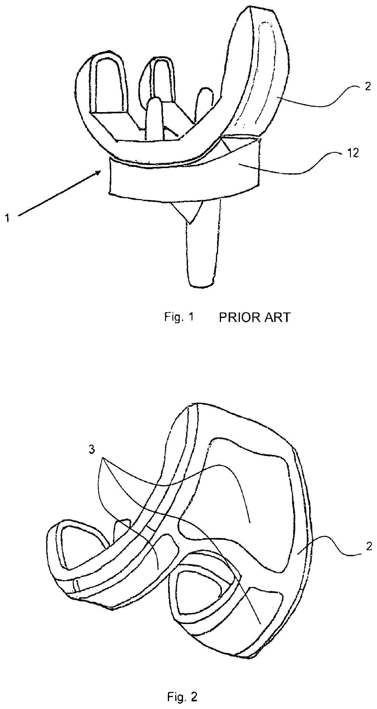
[0013]The drawing in FIG. 1 shows a knee endoprosthesis 1 according to the prior art in a perspective illustration. The implant is formed by a femur component with a base body 2 that consists of a ceramic material, as well as a tibia component 12 of which at least the area facing toward the femur component consists of polyethylene.

[0014]In comparison, FIG. 2 shows a femur component according to an embodiment of the present invention, with sliding tribological surfaces that are formed by inserts 3 of a ceramic material that are inserted in a base body 2. In the case of the example embodiment described here, zirconium dioxide was used for producing these inserts 3, but in the same manner the inserts 3 can however alternatively consist of an aluminum oxide ceramic or of a mixture of these two ceramics.

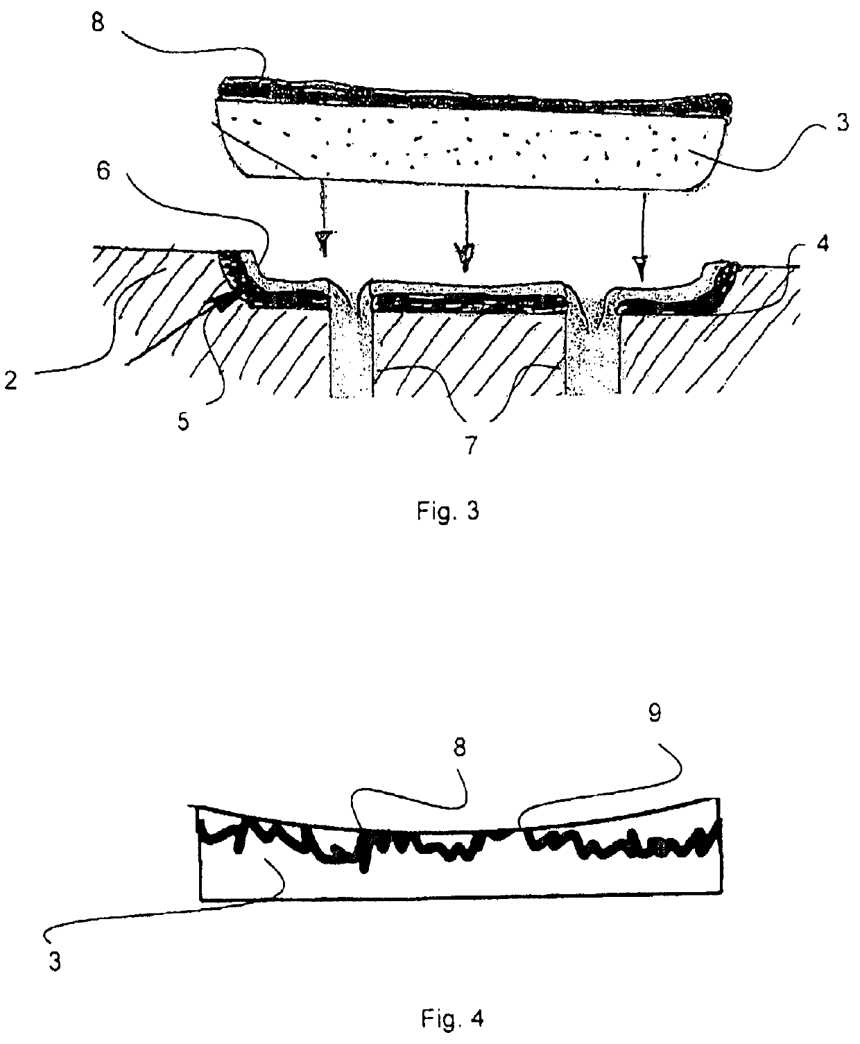
[0015]The ceramic inserts 3 are integrated in the manner of inlays in allocated “tub or trough shaped” receiver recesses 4 of a metallic base body 2 of the femoral component, wherein the ...


PUM

PropertyMeasurementUnit
Melting pointaaaaaaaaaa
Tribological propertiesaaaaaaaaaa
Surface roughnessaaaaaaaaaa

Abstract

An orthopedic implant in the form of a femoral component of a knee endoprosthesis has sliding tribological surfaces formed by inserts of a ceramic material based on zirconium dioxide or aluminum oxide, which are inserted and transition flushly into a metallic base body. The inserts are connected to the base body by a silicate ceramic solder, which is solidified or hardened in a ceramic firing, and by a silicate glass solder. Discharge channels in the metallic base body help to produce a homogeneous glass solder layer and to avoid an excessively intense heat treatment of the solder connection, which could lead to fractures in the titanium oxide layer of the base body. Because a coating of a softer glass solder may be additionally provided on the sliding tribological surfaces of the inserts, the abrasive wear is further reduced and the service life is further increased.

Description

FIELD OF THE INVENTION[0001]The invention relates to an orthopedic implant in the form of a knee endoprosthesis with a femoral component that has sliding tribological surfaces formed by ceramic inserts that are inserted and glass-soldered in a metallic base body.BACKGROUND INFORMATION[0002]In the artificial replacement of a knee joint, the impaired joint surfaces are removed and replaced by two implants that are independent of one another on the tibial and femoral side, that is to say on the upper end of the shin bone (tibia) and on the lower end of the thigh bone (femur). In that regard, the joint surface replacement on the femoral side is served by an implant that, for most known implants, consists either of a special high strength titanium alloy or of a cobalt-chromium alloy, which are cast or forged and thereafter polished. In that regard, the tibial joint side is replaced by an implant consisting of the titanium or cobalt-chrome alloy, and generally a polyethylene insert is sec...

Claims


Application Information

Patent Timeline
IPC IPC(8): A61F2/38A61L27/18A61L27/10A61L27/06A61L27/30A61F2/30
CPCA61L27/06A61L27/30A61L27/10A61F2/3859A61L27/105A61L27/18A61F2002/30451A61F2310/00239A61F2310/00179A61F2002/30733A61F2002/30934A61F2220/0058A61F2002/30805A61F2310/00203A61F2310/00023A61F2310/00634A61L2430/24
Inventor MITROVIC, MILIJA
Owner ZM PRAZISIONSDENTALTECHN
Learn More