Hydraulic circuit for use on CVT vehicle

a hydraulic circuit and vehicle technology, applied in the direction of positive displacement liquid engine, machine/engine, servomotor, etc., can solve the problems of hydraulic noise, inefficient pressure reduction valve, and high output of non-adjustable positive displacement charge pump, so as to reduce unwanted hydraulic noise, increase overall fuel economy, and save engine power

Active Publication Date: 2020-05-19
BLUE LEAF I P INC
View PDF17 Cites 1 Cited by
  • Summary
  • Abstract
  • Description
  • Claims
  • Application Information

AI Technical Summary

Benefits of technology

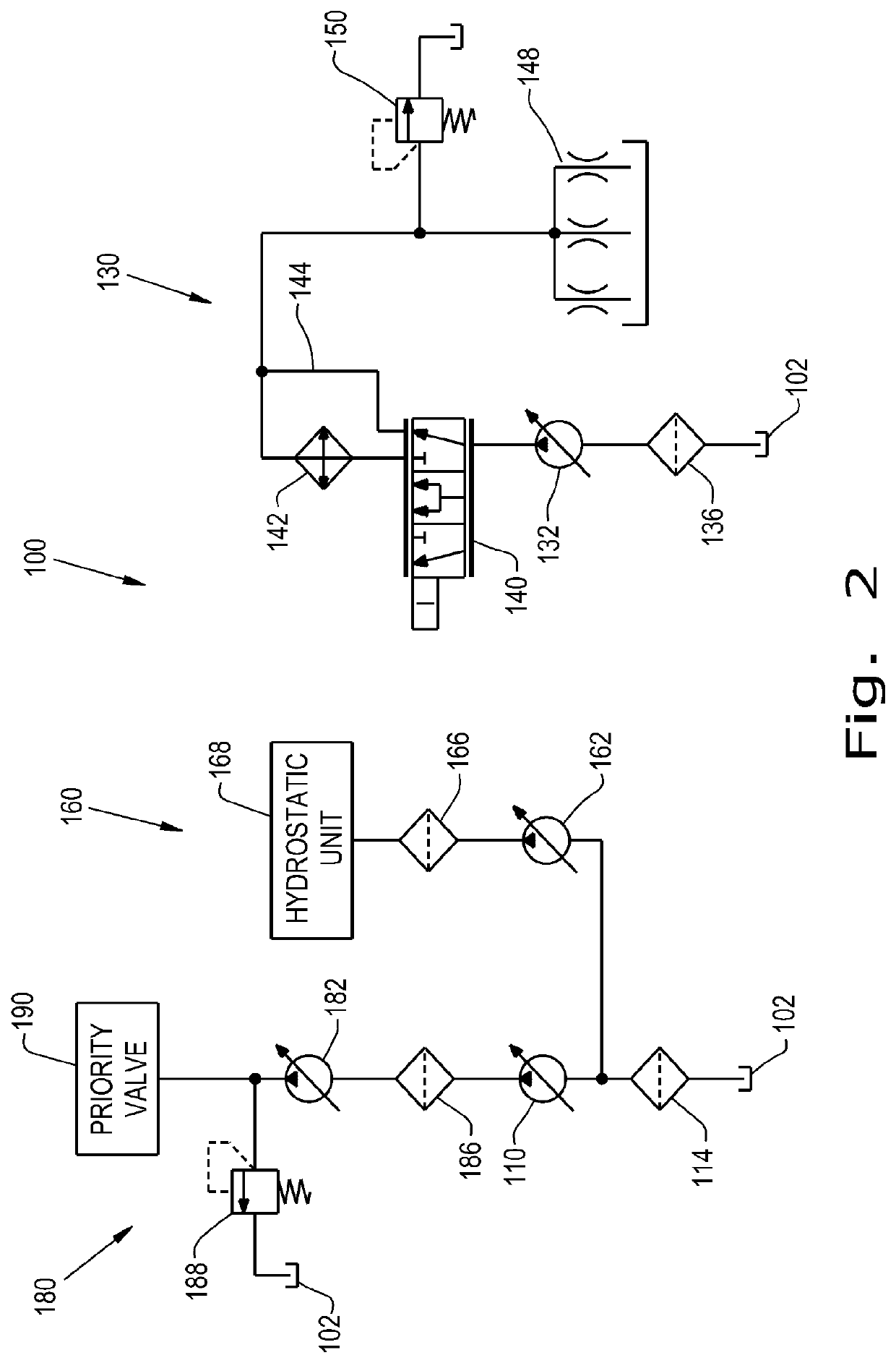
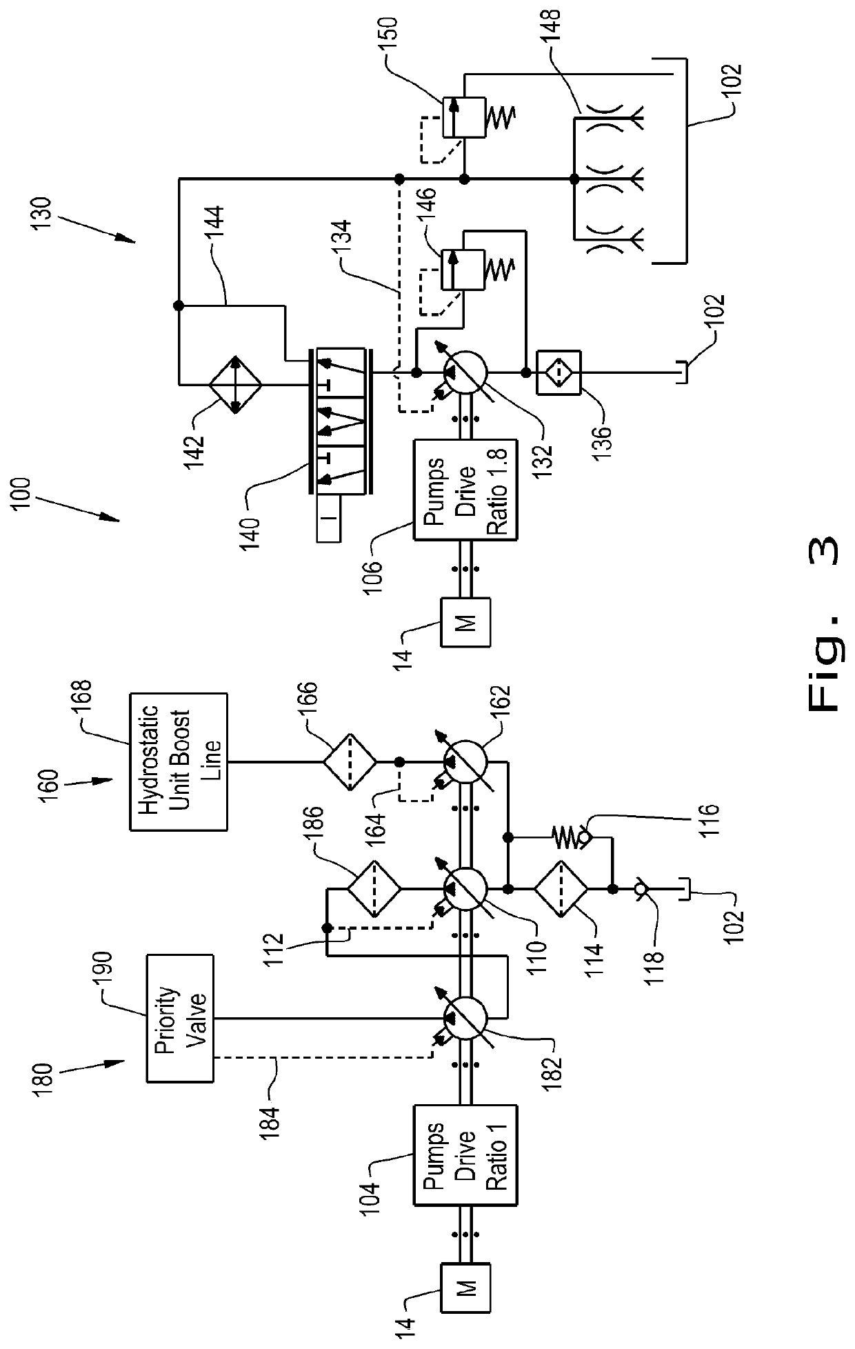
[0013]An advantage of the present invention is that it provides the needed three levels of hydraulic pressure and flow without excessively recirculating pressurized hydraulic fluid, thereby minimizing unwanted hydraulic noise, conserving engine power, and increasing overall fuel economy. Another advantage is that the present invention avoids unnecessary heating of the hydraulic fluid, while controlling the amount of hydraulic fluid that passes through the hydraulic oil cooler so that the hydraulic circuits are cooled according to their actual requirements, thereby further reducing hydraulic noise and energy wasting unneeded circulation.
[0014]A further advantage of the present invention is that the pumps may be sized and operated at their greatest efficiency. A further advantage of the present invention is that the hydraulic fluid is only pressurized to the level needed by each circuit of the system. A further advantage of the present invention is that each pump is driven by the engine of the work vehicle at a ratio that is most appropriate for that pump. A further advantage of the present invention is that it allows for more sophisticated control of each variable displacement pump, and thereby more efficient control of the hydraulic circuits. A further advantage of the present invention is that each hydraulic circuit reacts to instantaneous flow and pressure requirements, with the pumps adjusting to flow demand. Because of the dedicated pump size and pressure thresholds, an overall reduction of pressure deltas across the hydraulic circuits is achieved.

Problems solved by technology

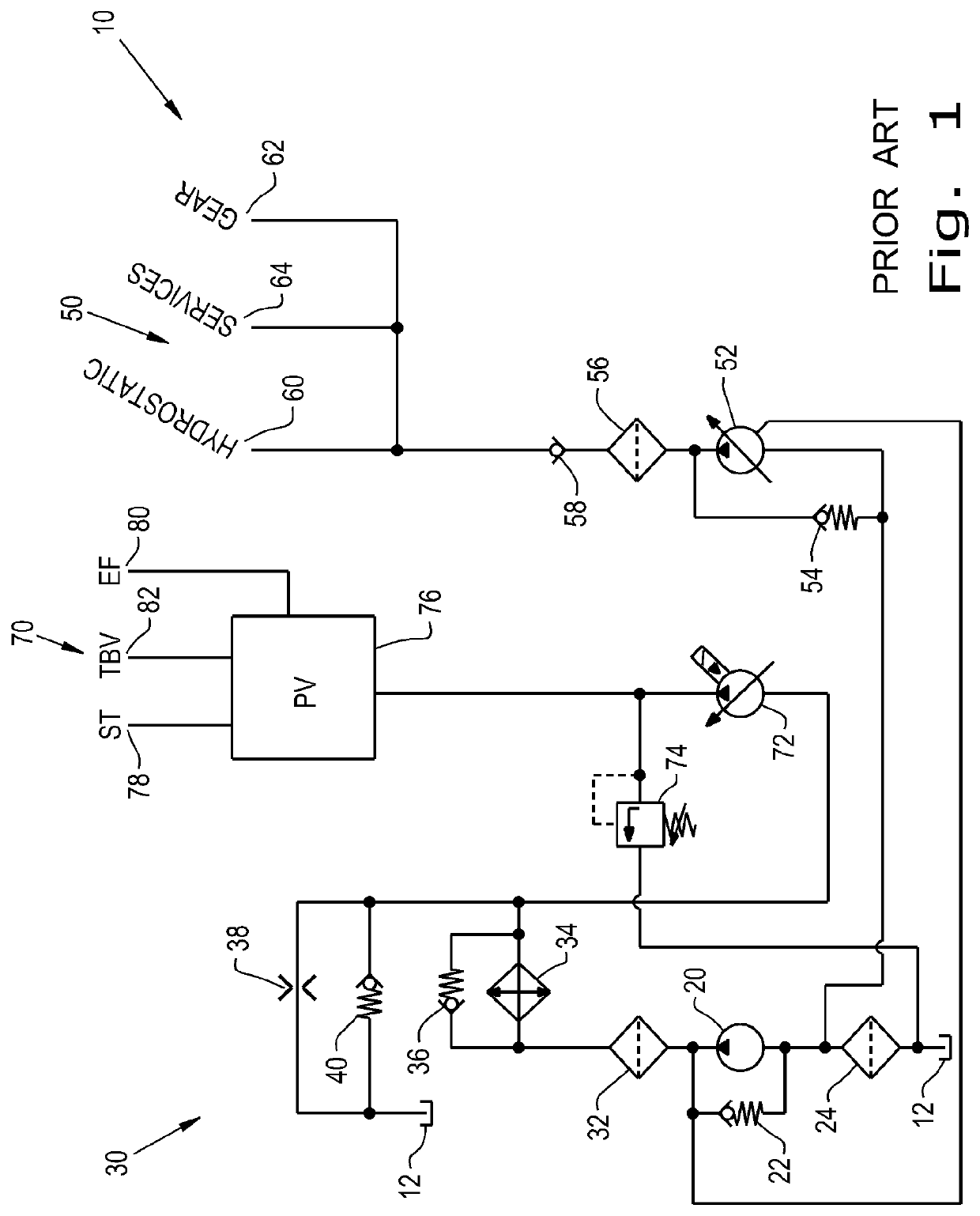
As a result, much of the output of the non-adjustable positive displacement charge pump was often wasted, recirculating all flow not required at a particular moment by the lubrication circuits, the medium pressure pump, or the high pressure pump.
Further, some of the output of the non-adjustable positive displacement charge pump that was in fact being used, required the use of inefficient pressure reducing valves due to the design of the known hydraulic systems.
This wasted output and the unneeded pressurization, and possibly de-pressurization and / or re-pressurization, directly results in hydraulic noise, wasted engine power, fuel inefficiency, and unnecessary heating of the hydraulic fluid.
Further, insofar as the lubrication circuits required hydraulic supply at a given moment, the non-adjustable positive displacement charge pump raised the hydraulic pressure unnecessarily high, requiring the aforementioned pressure reducing valve, and further contributing to power losses and heating.
Furthermore, the amount of hydraulic fluid passing through the hydraulic oil cooler was only passively controlled by the relative pressure drops across components of the hydraulic system, so that sometimes too little flow and often too much flow passed through the hydraulic oil cooler.
This further resulted in hydraulic noise and inefficiency, along with insufficient or excessive cooling of the hydraulic fluid.

Method used


Image

  • Hydraulic circuit for use on CVT vehicle
  • Hydraulic circuit for use on CVT vehicle
  • Hydraulic circuit for use on CVT vehicle

Examples


Embodiment Construction

[0021]The terms “continuously variable transmission,”“infinitely variable transmission,”“hydrostatic transmission,”“engine,” and “drive wheels” are used principally throughout this specification for convenience but it is to be understood that these terms are not intended to be limiting. Thus, “continuously variable transmission,”“infinitely variable transmission,” or “hydrostatic transmission” refers to a variable transmission requiring hydraulic flow and / or pressure, but should not be construed as limiting and may represent any variable ratio connection between a power supply and a motion output, such as wheels. “Engine” refers to an internal combustion engine, but should not be construed as limiting and may represent an external combustion engine, an electric, hydraulic, or pneumatic, or other rotational power producing device. “Drive wheels” refers to round wheels, but again, they should not be construed as limiting and may represent tracks or other ground running tractive device...


PUM


Abstract

A hydraulic system for a work vehicle has a high pressure circuit for providing high pressure hydraulic fluid, a medium pressure circuit for providing medium pressure hydraulic fluid, and a low pressure hydraulic circuit for providing low pressure hydraulic fluid. The high pressure circuit has a variable displacement charge pump that provides pressurized hydraulic fluid only to a high pressure variable displacement pump according to demand, which provides the further pressurized hydraulic fluid to a priority valve according to demand. The medium pressure circuit has a medium pressure variable displacement pump that provides pressurized hydraulic fluid according to demand. The low pressure circuit has at least one low pressure variable displacement pump that provides pressurized hydraulic fluid by way of an oil cooler and / or an oil cooler bypass controlled by a proportional valve.

Description

BACKGROUND OF THE INVENTION[0001]The present invention relates to vehicles having high pressure hydraulic circuits used for high pressure hydraulic devices such as hydraulic steering, brake valves, or hydraulic actuators, medium pressure hydraulic circuits used for a hydrostatic or geared transmission, and / or low pressure hydraulic circuits used for lubrication. More specifically, the present invention relates to work vehicles having high, medium, and low pressure hydraulic circuits.[0002]Work vehicles are used in many different vocations, including agriculture, construction, industrial, and forestry, as non-limiting examples. These work vehicles can take many forms, such as backhoe loaders, wheel loaders, forestry fellers, skidders, harvesters, sprayers, application equipment, utility vehicles, agricultural tractors, and compact tractors. Often, these work vehicles have multiple hydraulic devices with differing requirements in terms of pressure and flow in order to function correct...

Claims


Application Information

Patent Timeline
Patent Type & Authority Patents(United States)
IPC IPC(8): F15B11/17F16H57/04F16H61/4078F01M1/16F16H61/00F01M5/00F15B20/00F01M1/02E02F9/22F04B49/00F04B23/02F04B23/04
CPCF01M5/002F15B20/007F01M1/02F16H61/4078F04B23/02F04B23/04F16H61/0031F04B49/002F16H57/0441E02F9/22F16H57/0436F01M1/16F15B11/17F01M2001/0246E02F9/2296F01M2001/0253F16H2061/0037E02F9/2292
Inventor DIGESÙ, PASQUALEVESCOVINI, MAURIZIOCASALI, PAOLO
Owner BLUE LEAF I P INC
Why Eureka
Try Eureka