Joined incompatible metallic parts and method of joining

a technology of incompatible metallic parts and joints, applied in the direction of mechanical equipment, non-electric welding equipment, manufacturing tools, etc., can solve the problems of no literature work on friction stir welding of magnesium to copper, no high-production rate application, and the intermetallics are considered problematic for mg—fe, so as to reduce the fatigue life of the joint and improve the joint fatigue life

Active Publication Date: 2020-07-28
NAT RES COUNCIL OF CANADA
View PDF12 Cites 0 Cited by
  • Summary
  • Abstract
  • Description
  • Claims
  • Application Information

AI Technical Summary

Benefits of technology

[0019]Applicant has found a technique that improves the fatigue life of joints of metallic parts where the metals of the two parts are incompatible. By metallic part, a part is intended that has a composition, at least in the neighbourhood of the join (interface), with a metal fraction that is substantially uniformly distributed across the interface, such as in a metal matrix composite, cermet, or a part nominally composed of the metal. The metal / metal fraction refers to a pure metal, an alloy (solid state solution), or other relatively homogeneous mixture of metals, expressly including all Fe base alloys, all steels, all Al-base alloys, all Mg-base alloys, all Ti base alloys and all Cu-base alloys. ‘Compatible metal’ designates metals that do not form intermetallics that decrease a fatigue life of the join, when a temperature of the parts at the interface approaches a melting point of one of the metals, and incompatible metals form such intermetallics.
[0020]Unexpectedly, Applicant has found that by cold spraying a layer of a thickness (150-900 μm, more preferably 175-500 μm, most preferably 185-450 μm) which happens to be a more convenient, and cost effective, range of thicknesses for cold spraying than 8 μm or 5 mm, and using a lap FSJ configuration, delamination of the joint is avoided during the FSJ, and intermetallics are substantially suppressed, resulting in a higher fatigue resistance. Specifically the cold spray layer is applied on a 1st part, which has a higher resistance to plasticization, so that friction stir welding is performed through the 2nd part, which is more amenable to FSJ. The cold spray deposition is made of a third metal compatible with the 2nd part, and preferably has an equally low resistance to plasticization as the 2nd part, whereby it is subject to greater plastic deformation with lower inertia collisions and is thus easily cold sprayed. The third metal may be the same metal as that of the 2nd part, or may be a different alloy of the same base metal, or may be a different, compatible metal.
[0021]By lap joining, herein is intended a process in which a shoulder of the friction stir tool meets only the 2nd part (i.e. does not meet the 1st part or cold sprayed layer) and (at least a substantial component of) a down force of the FSJ process, applied by the shoulder, pushes the 2nd part toward the coated 1st part. The substantial component may be provided by ensuring a mean angle between a rotary axis of the tool with respect to a normal of the first part is within −60° to 60′, more preferably from −45° to 45′, throughout the process. This contrasts the butt joining process shown FIG. 1. of Champagne III et al., and includes the FIG. 1 of Haghshenas et al. A consequence of the lap joining arrangement, as opposed to a butt joining arrangement, is that forces of the FSJ process do not tend to separate the parts. By keeping a minimum mean distance of at least 300 μm between the FSW tool tip and the metal of the 1st part, formation of intermetallics of the metal of the 1st part with that of the 2nd part and the third metal can be avoided or minimized during the plasticization of the second metal, and at least some of the cold sprayed third metal.

Problems solved by technology

Unfortunately intermetallics are produced by joining most metals.
As most Mg alloys contain appreciable amounts of aluminum as a main alloying element, these intermetallics are considered problematic for Mg—Fe.
Mg—Cu: No literature work has been found on friction stir welding of magnesium to copper due to a lack of industrial relevance.
Unfortunately, this technique is applicable only to applications that can afford the time to deposit an 8.5 mm coating by cold spray (or at least a 5-25 mm as per FIG. 1).
If a cold spray layer of at least 5 mm is required for FSW bonding, there may be no high-production-rate application for this joining, because the time required to develop a 5 mm cold spray layer is incompatible with low cost production.
When the 22MnB5 sheets were heat treated, the appearance of the coating had changed and it would not facilitate joining when using the friction stir welding parameters studied here.
Modification of this Al-12Si coating after heat treatment by light abrasion or chemical pickling with HCl solution also failed to promote adhesion during friction stir welding.
In the case of joining steel and aluminum parts, if the FSW tool enters the steel, it can improve an initial bond strength of the join, but it severely decreases a longevity and expense of the FSW tools used, as suggested by Haghshenas et al.
Furthermore, the mixing of steel with aluminum leads to poor fatigue resistance for the join.
Thus joins of a variety of metals that would desirably accomplished by FSW are prevented because of the formation of brittle intermetallics leads to joints that have poor longevity.

Method used


Image

  • Joined incompatible metallic parts and method of joining
  • Joined incompatible metallic parts and method of joining
  • Joined incompatible metallic parts and method of joining

Examples


example 1

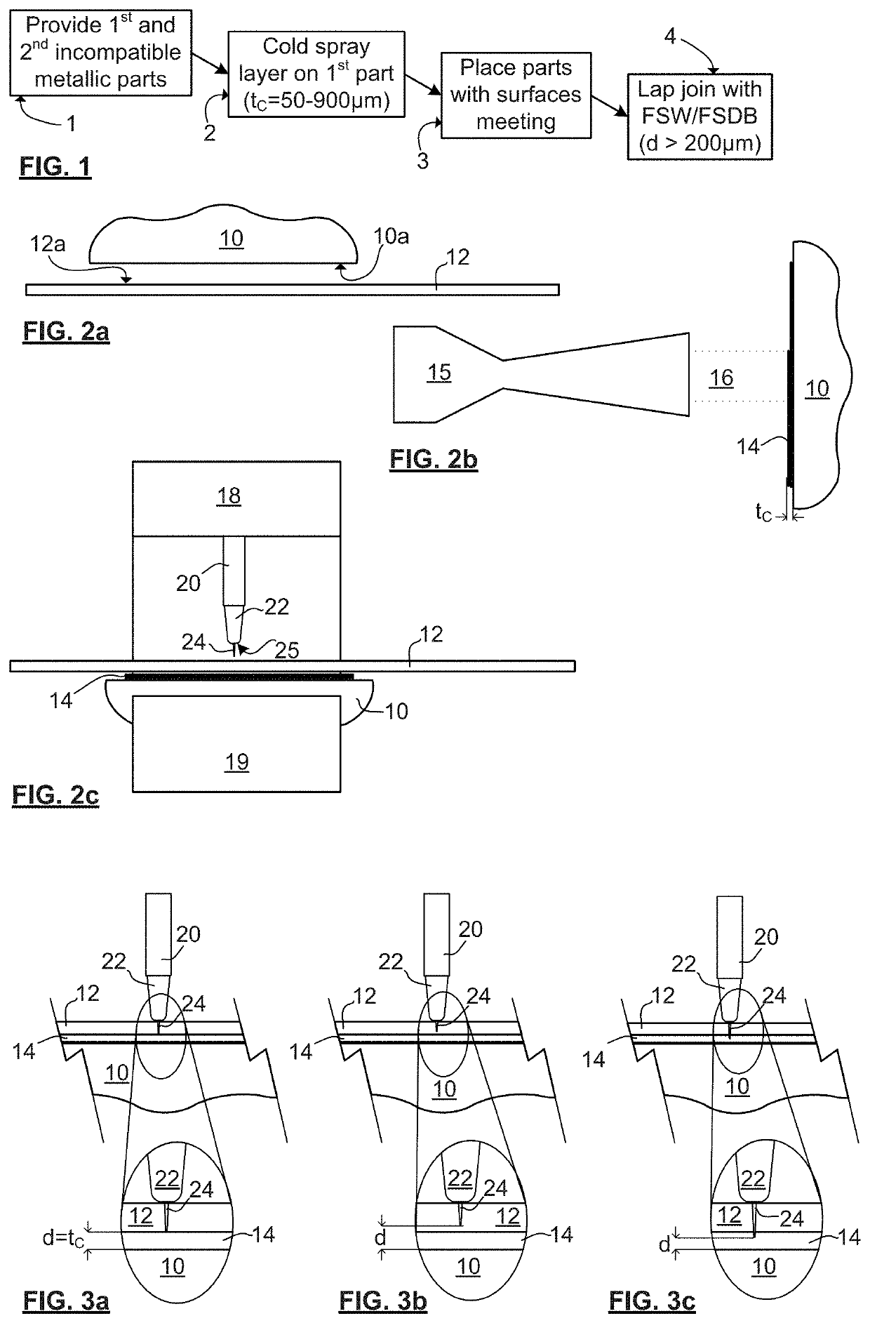
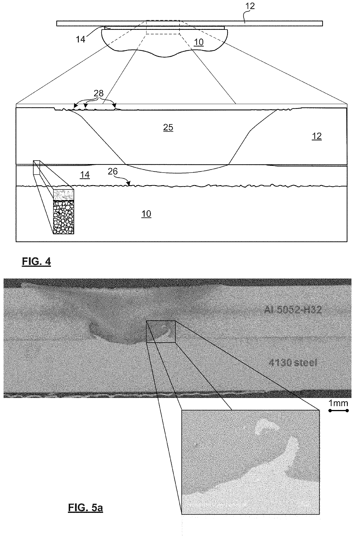
[0068]FIG. 5a is a micrograph showing a cross-section of a conventional Al-steel friction stir weld. An enlargement shows steel fragments that were entrained in a plasticization during the FSW process. These particles remain frozen in the otherwise Al matrix. The join of FIG. 5a was made using a conventional FSW approach, which means that a pin tool is designed to be slightly longer than the top sheet (generally between 0.3-1.0 mm longer). As the Al sheet was 3 mm thick, the tool pin length was 3.6 mm. The tool material can be a hardened steel (H13, D2, etc. . . . ) but wear issues are encountered doing so. It is preferable to use a W-based tool material to prevent tool wear although wear issues are still possible in a production environment with this material. This specific bond was created with a tool composed of W-15 / 20% Co. The W-based tool consisted of a conical pin without features, such as threads, flats or flutes, because these features are harder to manufacture in this mate...

example 2

[0076]A range of thicknesses of coatings, and plunge depths tool pin depths, were examined, and it was found that a distance d greater than 250 μm was critical for an lxxx series Al cold sprayed coating, and that a distance d of 550 μm was sufficient. As will be appreciated by those of skill in the art, other minimum distances may be required for other materials, and the minimum distance d can be determined for other material systems in a like manner, using ordinary skill in the art.

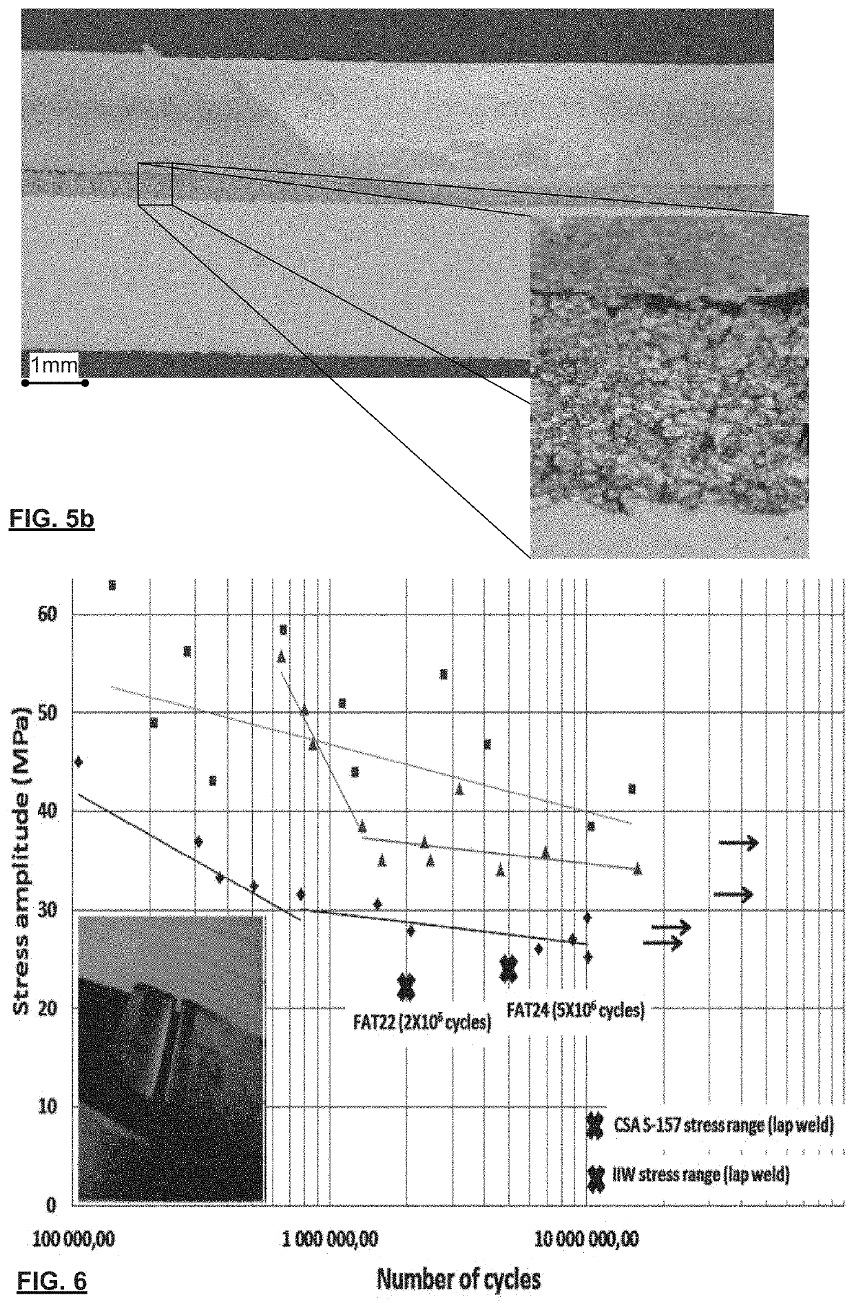
[0077]FIG. 7 includes micrographs of a first join and a second join, and respective enlargements, showing a join with a coating that failed during FSJ processing, in comparison with a working join. Both joins were made according to the method described in relation to FIG. 5b by cold spraying a layer deposited into a cold rolled steel sheet (low carbon steel). The only difference is that in the first join (top), the tool length was 2.15 mm, which penetrated into the cold sprayed Al coating by about 0.15 m...


PUM

PropertyMeasurementUnit
thickaaaaaaaaaa
wt. %aaaaaaaaaa
thickaaaaaaaaaa

Abstract

A technique for joining parts of incompatible metals involves cold spraying a 150-900 micron thick layer of a metal compatible with the second part onto the first part, and friction stir joining the parts by lap welding while keeping a tool of the FSJ tool at least 300 microns away from the first part (less layer) throughout the joining, to avoid damaging the cold spray to first part interface, and formation of intermetallics. Fatigue resistance was tested, with and without a sealant.

Description

CROSS-REFERENCE TO RELATED APPLICATIONS[0001]This application is a national phase entry of International Patent Application PCT / IB2016 / 056539 filed Oct. 28, 2016, which claims the benefit of U.S. Provisional Patent Application Ser. No. 62 / 248,574 filed Oct. 30, 2015.FIELD OF THE INVENTION[0002]The present invention relates in general to the joining of first and second incompatible metallic parts, and in particular to cold spraying a coating of a third metal compatible with the second part onto the first part, and friction stir joining the two parts together without letting a tool tip of the FSW tool getting closer than a given distance from first part less coating.BACKGROUND OF THE INVENTION[0003]Cold plastic deformation of metals is a wonderful thing. It allows for processing of metal below its melting point, avoiding a host of problems with the formation of intermetallics, and oxides, and has been developed in different processes including cold spray, and friction stir joining (FS...

Claims


Application Information

Patent Timeline
Patent Type & Authority Patents(United States)
IPC IPC(8): F16B5/08B23K20/24B23K20/233B23K20/227B23K20/12B23K20/16B23K101/18B23K103/08B23K103/10B23K103/12B23K103/14B23K103/18B23K103/20
CPCF16B5/08B23K20/2275B23K20/16B23K20/24B23K20/2333B23K20/1265B23K20/1225B23K2103/14B23K2103/20B23K2103/10B23K2103/18B23K2101/18B23K2103/15B23K2103/12
Inventor AMIRA, SOFIENEGOUGEON, PATRICKLEGOUX, JEAN-GABRIELNADEAU, FRANCOIS
Owner NAT RES COUNCIL OF CANADA
Why Eureka
Try Eureka