Assembly comprising a suction line, a pressure line and a pump

a technology of pressure line and suction line, which is applied in the direction of prosthesis, diagnostic recording/measuring, other blood circulation devices, etc., to achieve the effect of reducing the volume flow

Active Publication Date: 2020-08-04
XENIOS AG
View PDF18 Cites 1 Cited by
  • Summary
  • Abstract
  • Description
  • Claims
  • Application Information

AI Technical Summary

Benefits of technology

[0013]The discharge cannula makes it possible to return a flow of blood discharged from the heart in order to relieve the heart at the moment of the inflow through the arterial cannula. The discharge cannula can also be referred to as a relief cannula, and the discharge line can also be referred to as a relief line. In this case, the arterial cannula preferably already ends in the artery in front of the heart whereas the discharge cannula is pushed far into the heart. The discharge cannula therefore is at least 20% longer than the arterial cannula in practical applications.
[0016]In order to adjust the discharge intensity independently of the diameter of the discharge line, it is proposed that the discharge line features a flow restrictor. This flow restrictor can reduce the volume flow conveyed through the discharge line in order to adjust a more or less intense discharge at the heart.
[0017]It is particularly advantageous if the control makes it possible to automatically adjust the flow restrictor in dependence on the pulsating flow. This makes it possible to cause a discharge during a pressure increase of the pulsatile pump and to control or adjust the moment of the discharge in dependence on the moment of the pressure increase and, in particular, in dependence on the pumping rhythm of the heart.
[0019]The connection of the discharge line to the pressure or suction line by means of a Y-adapter alone ensures that the discharge cannula causes the heart to be relieved by discharging blood. If the discharge line is connected to the pressure line, however, it is frequently advantageous if the discharge line features a check valve. This prevents the pump from pumping blood into the discharge line.

Problems solved by technology

Additional lumens or channels are not required and even disadvantageous.

Method used


Image

  • Assembly comprising a suction line, a pressure line and a pump
  • Assembly comprising a suction line, a pressure line and a pump
  • Assembly comprising a suction line, a pressure line and a pump

Examples


Embodiment Construction

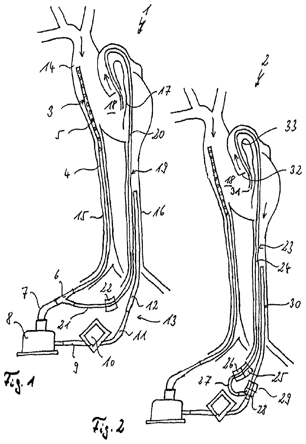
[0036]According to the first exemplary embodiment illustrated in FIG. 1, the extracorporeal life support system 1, 2 has a suction line 3 that features a venous cannula 4 with bores 5, a Y-adapter 6 and a feed line 7 leading to a pump 8. Only the pump head of the pump 8 is illustrated in this figure. The pump 8 is connected to an oxygenator 10 by means of a connecting line 9, wherein the oxygenator is connected to an arterial cannula 12 by means of a delivery line 11. The delivery line 11 and the arterial cannula 12 form a pressure line 13.

[0037]While the assembly is in use, blood can therefore be drawn from the heart 14 to the pump 8 through the vena femoralis 15 by means of the venous cannula 4 of the suction line 3 in order to be subsequently conveyed into the left ventricle via the oxygenator 10 and the arterial cannula 12, namely through the arteria femoralis 16 and the aorta via the aortic arch. In this way, the heart 14 is bypassed and therefore relieved.

[0038]If a pulsatile ...


PUM


Abstract

An assembly for an extracorporeal life support system with a suction line that features a venous cannula and a pressure line that features an arterial cannula furthermore includes a pump that is arranged between the suction line and the pressure line. This assembly has a discharge line with a discharge cannula, wherein the discharge cannula is longer than the arterial cannula, and wherein the discharge line is connected to the suction line or the pressure line.

Description

CROSS REFERENCE TO RELATED APPLICATIONS[0001]Applicant claims priority and this application is a continuation under 35 U.S.C. § 120 of International Application No. PCT / DE2016 / 000025 filed Jan. 26, 2016, which claims priority under 35 U.S.C. § 119 of German Application No. 10 2015 000 771.8 filed on Jan. 26, 2015. The International Application under PCT article 21(2) was not published in English. The disclosures of the aforesaid International Application and German application are incorporated herein by reference.BACKGROUND OF THE INVENTION1. Field of the Invention[0002]The invention pertains to an assembly with a suction line that features a venous cannula, a pressure line that features an arterial cannula and a pump that is arranged between the suction line and the pressure line.[0003]Such assemblies are used for extracorporeal membrane oxygenation or for extracorporeal lung assist. In extracorporeal membrane oxygenation, cannulas are inserted into two large blood vessels. The ECM...

Claims


Application Information

Patent Timeline
Patent Type & Authority Patents(United States)
IPC IPC(8): A61M37/00A61M1/36A61M1/10A61M60/109A61M60/247A61M60/38A61M60/435A61M60/515A61M60/538A61M60/851
CPCA61M1/3659A61M1/1008A61M1/3666A61M1/3667A61M1/1086A61M1/1001A61M1/10A61M1/1005A61M2230/04A61M60/38A61M60/851A61M60/247A61M60/109A61M60/538A61M60/515A61M60/435
Inventor SIMUNDIC, IVOMATHEIS, GEORGOSTADAL, PETR
Owner XENIOS AG
Why Eureka
Try Eureka