
Cylindrical printing plate, cylindrical printing plate precursor, method for manufacturing cylindrical printing plate precursor, and method for manufacturing cylindrical printing plate

a technology of cylindrical printing plate and precursor, which is applied in the direction of plate printing, foil printing, printing, etc., can solve the problems of deterioration of the print quality of the cylindrical printing plate, deterioration of the solid image area compared to the sheet-like printing plate, and poor quality of the halftone dot, so as to achieve excellent solid density and high halftone dot quality , excellent print medium followability and printing durability

Active Publication Date: 2020-10-20
FUJIFILM CORP
View PDF20 Cites 0 Cited by
  • Summary
  • Abstract
  • Description
  • Claims
  • Application Information

AI Technical Summary

Benefits of technology

This configuration enables excellent solid density, high halftone dot quality, improved print medium followability, and printing durability by optimizing pressure distribution and ink transfer.

Problems solved by technology

In a cylindrical printing plate formed from such a seamless cylindrical printing plate precursor, it is found that since the film thickness of the relief forming layer of the sheet-like printing plate is thick and pressure is not sufficiently applied to an image area, the density of a solid image area (hereinafter, referred to as “solid density”) is deteriorated compared to the sheet-like printing plate.
On the other hand, in a case where pressure is applied to the image area by increasing the pressing amount at the time of printing to improve the solid density, halftone dots are largely deformed, the reproduction density of the minimum dot is increased, and thus there is a problem of deterioration in halftone dot quality.
Accordingly, there is an essential problem that the print quality of the cylindrical printing plate is deteriorated compared to a sheet-like printing plate.
However, since a sufficient pressure is not applied to a solid image area at the time of printing, a satisfactory solid density cannot be obtained, and in a case where printing is performed on a print medium having roughness, the followability of the plate (print medium followability) which follows the roughness on the print medium is not sufficient.
Therefore, it is not able to solve the problem that blur occurs in a printed material.

Method used


Image

  • Cylindrical printing plate, cylindrical printing plate precursor, method for manufacturing cylindrical printing plate precursor, and method for manufacturing cylindrical printing plate
  • Cylindrical printing plate, cylindrical printing plate precursor, method for manufacturing cylindrical printing plate precursor, and method for manufacturing cylindrical printing plate
  • Cylindrical printing plate, cylindrical printing plate precursor, method for manufacturing cylindrical printing plate precursor, and method for manufacturing cylindrical printing plate

Examples


example 1

[0340][Production of Cylindrical Printing Plate Precursor]

[0341]

[0342](Preparation of Resin Composition A to Form First Hard Layer of Relief Forming Layer)

[0343]Using an MS type small pressurizing kneader (manufactured by MORIYAMA CO., LTD.) 100 parts by mass of syndiotactic 1,2-polybutadiene RB820 (manufactured by JSR Corporation) as a crystalline polymer, and 12 parts by mass of CARBON BLACK #45L (average particle diameter: 24 nm, relative surface area: 125 m2 / g, manufactured by Mitsubishi Chemical Corporation) as carbon black were kneaded for 10 minutes at 80° C. with a front blade at 35 rpm and a rear blade at 35 rpm and then the kneaded product was cooled to 60° C. 1.5 parts by mass of PERCUMYL D-40 (organic peroxide, dicumyl peroxide (40% by mass), manufactured by NOF CORPORATION) as a thermal polymerization initiator was added thereto, and kneaded for 10 minutes at 60° C. with a front blade at 20 rpm and a rear blade at 20 rpm to prepare a resin composition A to form a first ...

example 2

[0368]A cylindrical printing plate was produced in the same manner as in Example 1 except that in the preparation of the resin composition to form the first hard layer of the relief layer, the amount of PERCUMYL D-40 added was changed to 1.8 parts by mass to prepare a resin composition D, and a cylindrical printing plate in which the hardness K1 of the first hard layer was 19 MPa was obtained.

example 3

[0369]A cylindrical printing plate was produced in the same manner as in Example 1 except that in the preparation of the resin composition to form the first hard layer of the relief layer, the amount of PERCUMYL D-40 added was changed to 1.0 part by mass to prepare a resin composition E, and a cylindrical printing plate in which the hardness K1 of the first hard layer was 10 MPa was obtained.


PUM

PropertyMeasurementUnit
thicknessaaaaaaaaaa
thicknessaaaaaaaaaa
thicknessaaaaaaaaaa

Abstract

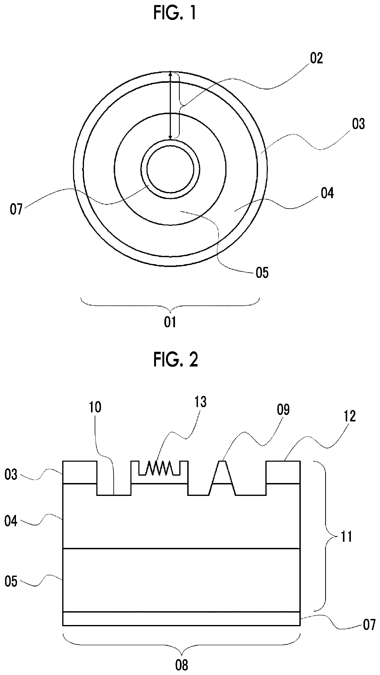
Provided is to provide a cylindrical printing plate with which printing of excellent solid density and high halftone dot quality is made possible, and further print medium followability and printing durability are excellent, a cylindrical printing plate precursor, a method for manufacturing a cylindrical printing plate precursor, and a method for manufacturing a cylindrical printing plate. A cylindrical printing plate includes a relief layer having a first hard layer, a soft layer, and a second hard layer in this order from a printing surface side, in which a hardness K1 of the first hard layer is 10 MPa or more and less than 20 MPa, a ratio K1 / K2 of the hardness K1 of the first hard layer with respect to a hardness K2 of the soft layer is 2.7 or more, a ratio K3 / K2 of a hardness K3 of the second hard layer with respect to the hardness K2 of the soft layer is 1.2 or more, a thickness of the first hard layer is 0.05 mm or more and 0.3 mm or less, and a thickness of the soft layer is 0.3 mm or more and 2.0 mm or less.

Description

CROSS-REFERENCE TO RELATED APPLICATIONS[0001]This application is a Continuation of PCT International Application No. PCT / JP2017 / 002523 filed on Jan. 25, 2017, which claims priority under 35 U.S.C. § 119(a) to Japanese Patent Application No. 2016-017784 filed on Feb. 2, 2016. The above application is hereby expressly incorporated by reference, in its entirety, into the present application.BACKGROUND OF THE INVENTION1. Field of the Invention[0002]The present invention relates to a cylindrical printing plate, a cylindrical printing plate precursor, a method for manufacturing a cylindrical printing plate precursor, and a method for manufacturing a cylindrical printing plate.2. Description of the Related Art[0003]In the flexographic printing and letterpress printing field, a letterpress printing plate on which a relief is formed imagewise has been used. As a plating making method for the printing plate used herein, for example, a method in which a printing plate precursor having a relief...

Claims


Application Information

Patent Timeline
Patent Type & Authority Patents(United States)
IPC IPC(8): B41N1/22B41C1/18B41N1/12B41C1/05B41C1/02
CPCB41N1/22B41C1/025B41C1/18B41C1/05B41N1/12
Inventor SHIRAKAWA, MASATONAMBA, YUSUKE
Owner FUJIFILM CORP
Learn More