Monolithic heat-exchanger bodies

Active Publication Date: 2020-11-10
GENERAL ELECTRIC CO
View PDF60 Cites 2 Cited by
  • Summary
  • Abstract
  • Description
  • Claims
  • Application Information

AI Technical Summary

Benefits of technology

The patent text describes a subject matter that will be explained in detail in a later section of the text. The technical effects of the subject matter include the ability to achieve certain technical objectives, which may be explained in the description or through practicing the subject matter.

Problems solved by technology

Power generation and distribution systems are challenged to provide improved power generation efficiency and / or lowered emissions.
Furthermore, power generation and distribution systems are challenged to provide improved power output with lower transmission losses.
However, closed cycle engine arrangements, such as Stirling engines, are challenged to provide relatively larger power output or power density, or improved efficiency, relative to other engine arrangements.
Closed cycle engines may suffer due to inefficient combustion, inefficient heat exchangers, inefficient mass transfer, heat losses to the environment, non-ideal behavior of the working fluid(s), imperfect seals, friction, pumping losses, and / or other inefficiencies and imperfections.

Method used


Image

  • Monolithic heat-exchanger bodies
  • Monolithic heat-exchanger bodies
  • Monolithic heat-exchanger bodies

Examples


Embodiment Construction

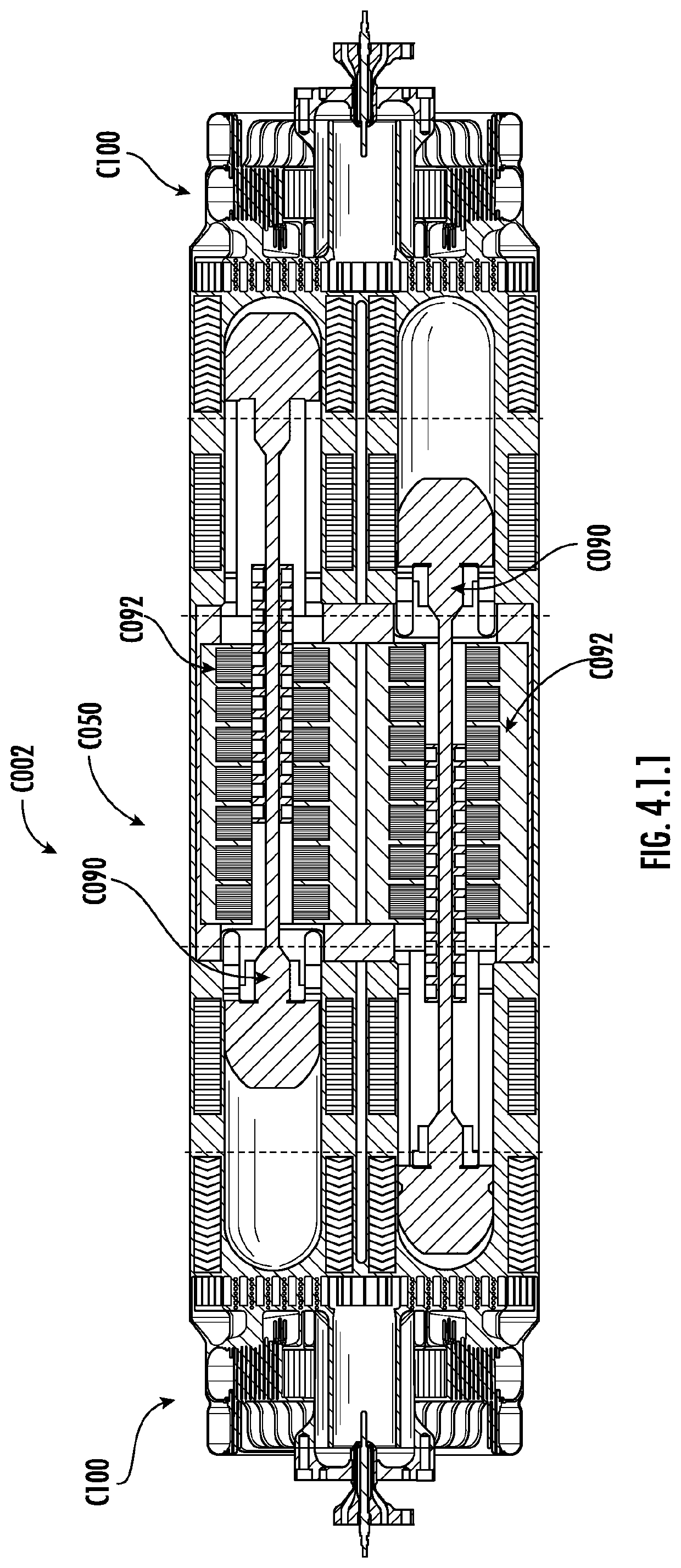
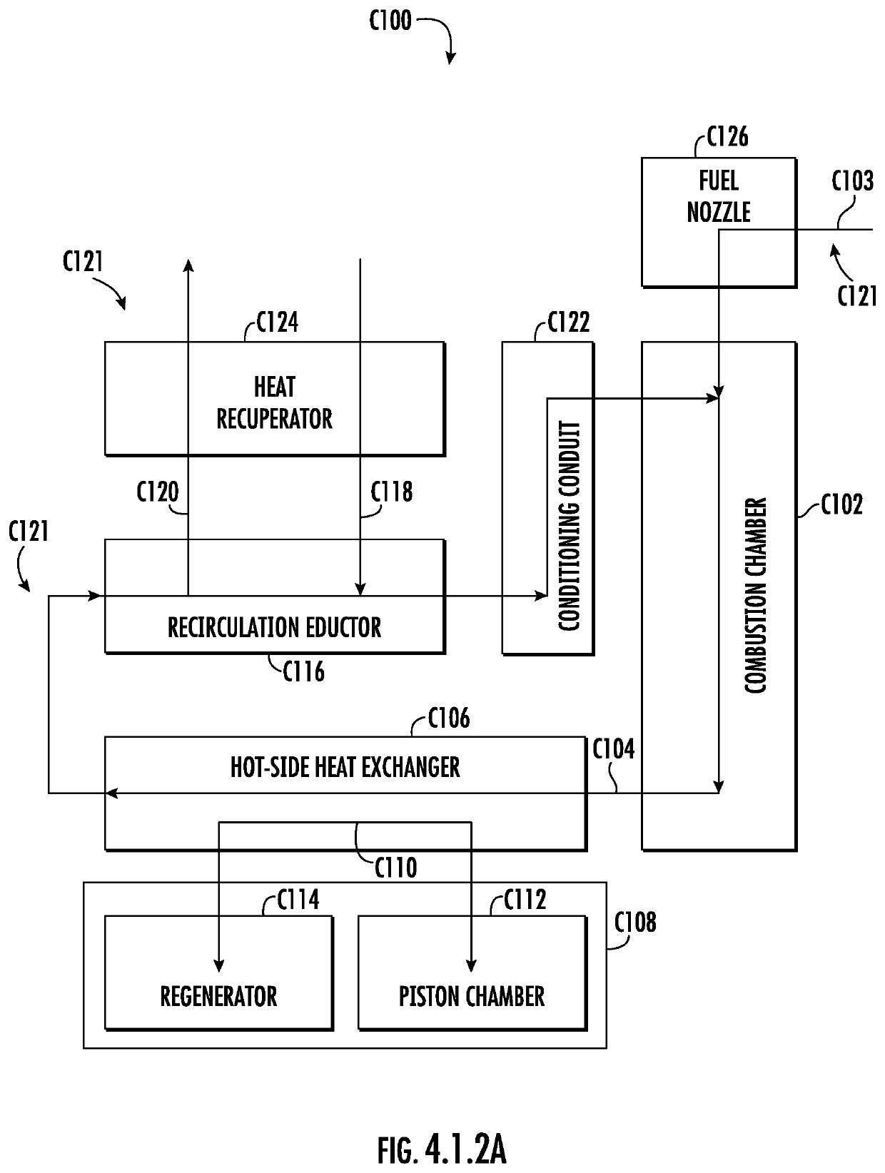
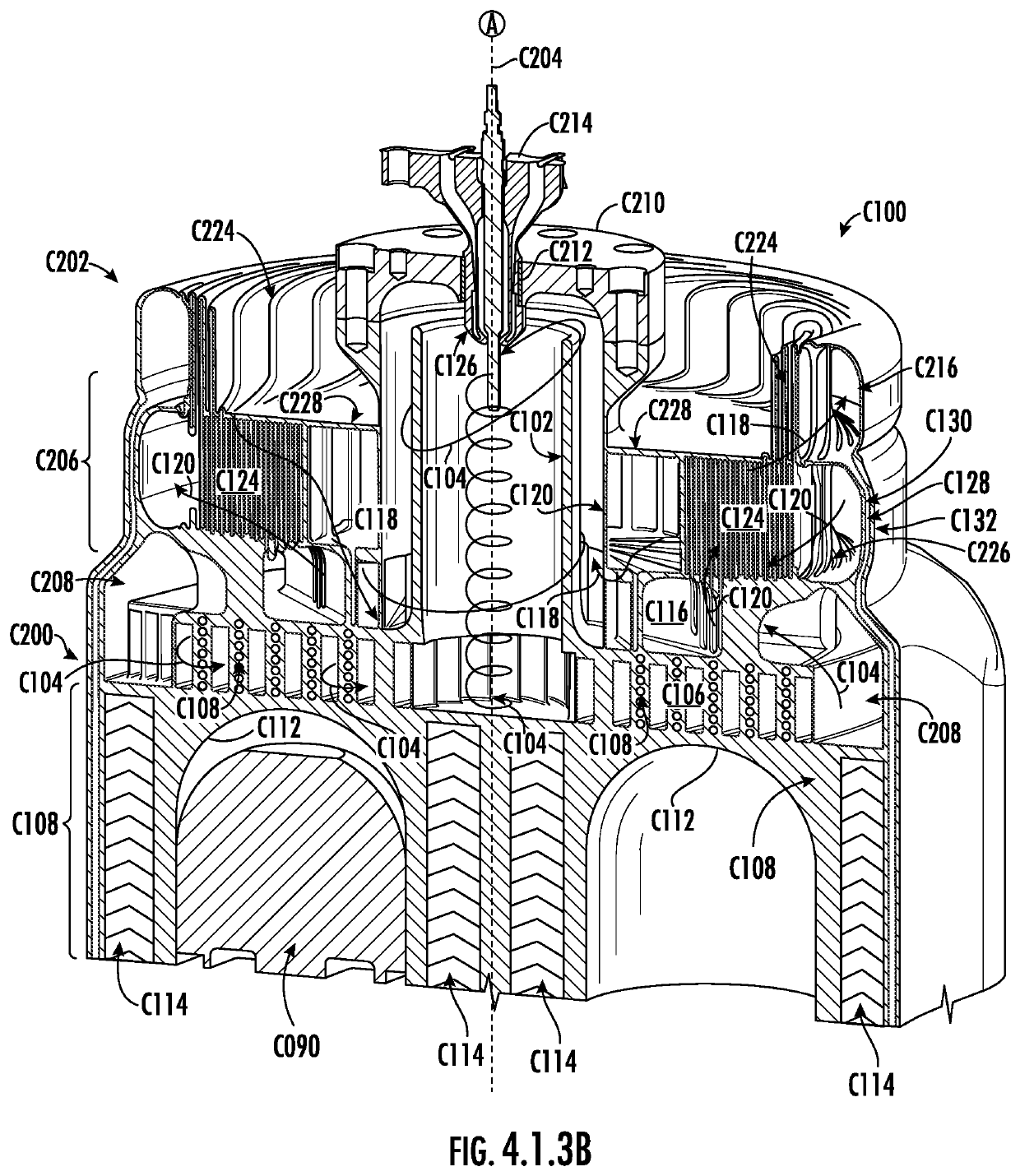
[0032]Reference now will be made in detail to embodiments of the disclosure, one or more examples of which are illustrated in the drawings. Each example is provided by way of explanation of the disclosure and not limitation. In fact, it will be apparent to those skilled in the art that various modifications and variations can be made in the present disclosure without departing from the scope of the disclosure. For instance, features illustrated or described as part of one embodiment can be used with another embodiment to yield a still further embodiment. In another instance, ranges, ratios, or limits associated herein may be altered to provide further embodiments, and all such embodiments are within the scope of the present disclosure. Unless otherwise specified, in various embodiments in which a unit is provided relative to a ratio, range, or limit, units may be altered, and / or subsequently, ranges, ratios, or limits associated thereto are within the scope of the present disclosure...


PUM


Abstract

A monolithic heat exchanger body includes a plurality of heating walls and a plurality of combustion fins. The plurality of heating walls are configured and arranged in an array of spirals or spiral arcs relative to a longitudinal axis. Adjacent portions of the plurality of heating walls respectively define a corresponding plurality of heating fluid pathways therebetween. The plurality of combustion fins are circumferentially spaced about a perimeter of an inlet plenum. The inlet plenum includes or fluidly communicates with a combustion chamber. The plurality of heating fluid pathways fluidly communicate with the inlet plenum. The plurality of combustion fins occupy a radially or concentrically inward portion of the monolithic heat exchanger body. The plurality of heating fluid pathways have a heat transfer relationship with a heat sink disposed about a radially or concentrically outward portion of the monolithic heat exchanger body. A plurality of conduction breaks disposed radially or concentrically outward relative to the plurality of combustion fins at least partially inhibit heat conduction from the plurality of combustion fins to the plurality of heating walls.

Description

CROSS-REFERENCE TO RELATED APPLICATIONS[0001]The present application claims priority to each of the following U.S. Provisional Applications, the contents of which are incorporated herein by reference in their entirety for all purposes as if set forth verbatim: App. No. 62 / 850,599, filed May 21, 2019; App. No. 62 / 850,623, filed May 21, 2019; App. No. 62 / 850,678, filed May 21, 2019; App. No. 62 / 850,692, filed May 21, 2019; and App. No. 62 / 850,701, filed May 21, 2019. The present application also incorporates by reference International Patent Application Number PCT / US2020 / 033674 filed on May 20, 2020 in its entirety for all purposes.FIELD[0002]The present subject matter relates generally to energy conversion systems, power generation systems, and energy distribution systems. The present subject matter additionally relates to heat exchangers and heat exchanger systems. The present subject matter further relates to piston engine assemblies, such as closed-cycle engine systems. The presen...

Claims


Application Information

Patent Timeline
IPC IPC(8): F02G1/055F28D9/04F28F13/14F28F7/02F28F13/00F02G1/04F02G1/043F28D21/00
CPCF28F13/003F02G1/055F02G1/04F28F13/14F28D9/04F28F7/02F02G2254/10F28F2210/10F28F2250/04F28D2021/0026F02G1/0435F02G1/044F02G1/045F02G1/047F02G1/057F23K5/20F23L15/02F23L15/04B33Y80/00F02G2244/00F02G2244/08F02G2255/10F02G2255/20F02G2256/02F02G2257/00F02G2275/20F02G2275/40F23R3/005Y02E20/34Y02T10/12F02G2244/50F02G2258/10F02G1/053F02G2243/00F02G2250/00F02G1/05F02G2270/80F02G2244/52F02G2280/10F02G2254/18F02G3/00F02G1/043F02G2244/54F02G2270/45F02G2270/40
Inventor MOOK, JOSHUA TYLERVANDEVOORDE, KEVIN MICHAELAKWARA, AIGBEDIONNOTARNICOLA, MICHAEL ROBERTBELLARDI, JASON JOSEPHSENNOUN, MOHAMMED EL HACINOSAMA, MOHAMEDNAGEL, ZACHARY WILLIAMMARRERO ORTIZ, VICTOR LUIS
Owner GENERAL ELECTRIC CO
Why Eureka
Try Eureka