
Process for forming graphene-coated particles

Active Publication Date: 2020-11-17
KING ABDULAZIZ UNIV
View PDF5 Cites 7 Cited by
  • Summary
  • Abstract
  • Description
  • Claims
  • Application Information

AI Technical Summary

Benefits of technology

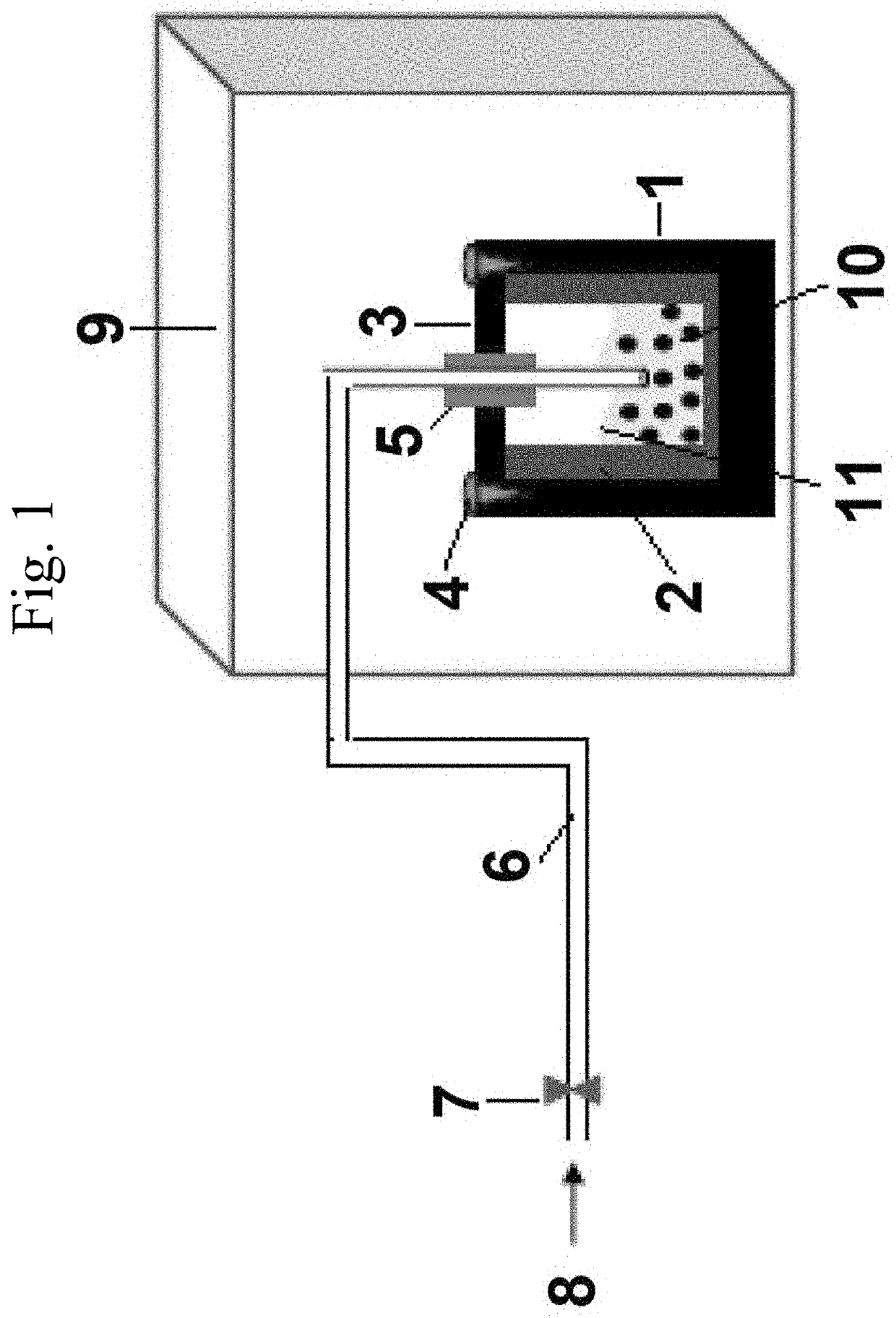
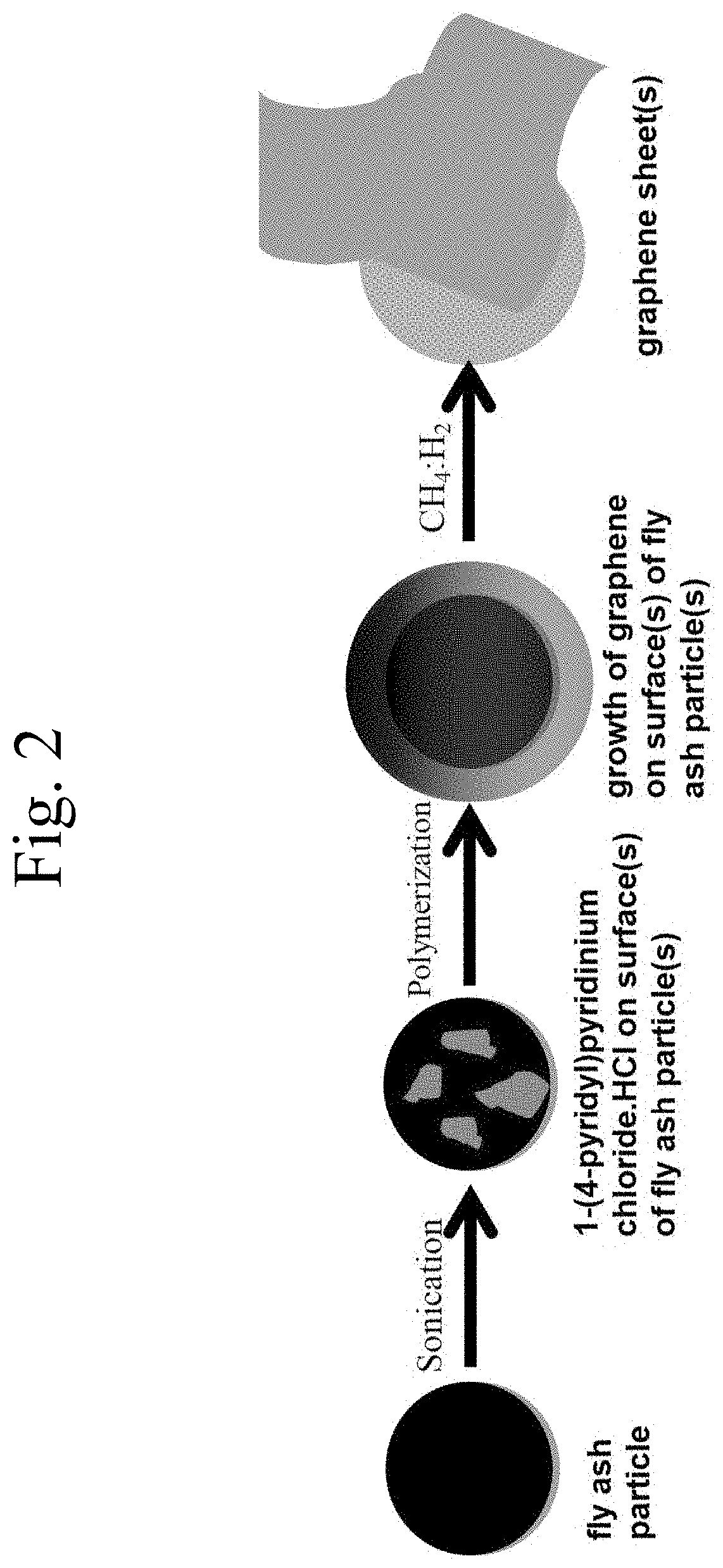
The invention provides methods for making graphene by reacting fly ash with a charged heteroaromatic compound and a solvent, and then contacting it with a gas stream containing CH4 and / or H2. The methods may be modified by adding a polymer-supported oxidizing agent and a sheath to the reaction. The resulting graphene has a unique structure and properties that make it useful in various applications. The invention also includes devices for producing graphene using a reaction vessel, heating apparatus, and a pipe with a valve for regulating gas flow.

Problems solved by technology

Such ash is often classified as hazardous waste.
The facile and low cost production of graphene by is a challenging matter facing the market.

Method used


Image

  • Process for forming graphene-coated particles
  • Process for forming graphene-coated particles
  • Process for forming graphene-coated particles

Examples


example 1

[0059]Preparation of Graphene

[0060]About 100 mg of fly ash and 200 mg of 1-(4-pyridyl)pyridinium chloride HCl were added to a glass beaker containing 50 mL of ethanol to give a mixture. The mixture was sonicated for 30 minutes at 60° C., then 150 mg of poly(4-vinylpyridinium chlorochromate) were added and the whole mixture was stirred for 40 minutes at room temperature (T ˜22° C.). After stirring for 40 minutes, the whole mixture was transferred to the exemplary reactor system depicted in FIG. 1. The system sealed and the temperature was raised to 160° C. for 60 minutes. During the heated reaction, dilute methane in hydrogen gas was bubbled through the mixture with flow rate of 5:95 sccm (standard cm3 / minute) for 10 seconds as the only gasses present during the reaction. After 60 minutes at 160° C., the reaction was stopped by quenching the reactor cylinder in an ice bath at 4° C. for 10 minutes, resulting in a suspension. The suspension was collected via centrifugation at 15000 rpm...

example 2

[0061]The influence of CH4:H2 gas ratio on the growth of graphene: The experiment in Example 1 was repeated under the same conditions except that the ratio of flow rates of CH4:H2 was varied at 5:25, 5:55, 5:75 or 5:95 sccm (standard cm3 / minute), and the reaction carried out at 50° C. The Raman spectra for the graphene produced as described above at the varied flow rate ratios were measured and depicted in FIG. 4.

example 3

[0062]The influence of temperature on the growth of graphene: The experiment in Example 1 was repeated under the same conditions except that the reaction was carried out at varied temperatures, i.e., 60, 85, 100, and 160° C. The Raman spectra for the graphenes produced in Example 3 at these varied temperatures were measured and are shown in FIG. 5.

[0063]Aspects of the invention provide methods for preparing graphene using fly ash in a thermal reactor. The thermal reactor may include a cylindrical tube with capacity of 80±5, 10, 15, or 25 cm3, which tube may be coated on an inside wall with a fluoropolymer film, such as PTFE, and the reactor may include a cover including one or more orifices to allow one or more silica or silicon tubes to pass through the orifice such that a gas may flow into the reaction chamber and / or through the solvent containing the reactants. The thermal reactor located in an electric oven, a gas-fired oven a coal-fired oven, a heating mantle, a heat exchange f...


PUM


Abstract

Methods of forming graphene may include reacting a dispersed mixture, comprising fly ash, a charged heteroaromatic compound, particularly a pyridinium compound, such as a 1-(4-pyridyl)-pyridinium salt, and a solvent, particularly an alcohol, such as ethanol, with a polymeric oxidizing agent, preferably polymer-supported pyridinium chlorochromate, to form a second mixture; and contacting the second mixture at a temperature of 120 to 180° C. with a gas stream comprising at least 0.1 vol. % CH4 and at least 10 vol. % H2 to form graphene on the fly ash. Methods of managing waste may comprise using fly ash waste to produce graphene. Devices for implementing such methods may involve steel cylindrical reaction vessels including a cover through which a valve-stoppable pipe is fed, which reaction vessel is at least partially surrounded by a heating device, and suitable for handling solvent and fly ash, as well as for receiving gas inflow through the pipe.

Description

CROSS-REFERENCE TO RELATED APPLICATIONS[0001]The present application is a Continuation of Ser. No. 16 / 510,080, pending, having a filing date of Jul. 12, 2019.BACKGROUND OF THE INVENTIONField of the Invention[0002]The present disclosure relates to the preparation of graphene, preferably by using fly ash, as well as such graphene materials themselves and their uses, in addition to methods of managing waste.Description of the Related Art[0003]Fly ash or flue ash is a coal combustion product, e.g., from the combustion of coal in coal-fired power plants. Flue ash is made up of particulates from the combustion, including fine particles of burned fuel and minerals, that are driven out of coal-fired boilers together with the flue gases. Fly ash can be captured by electrostatic precipitators or other particle filtration equipment, e.g., before the flue gases reach the chimneys, and / or can be collected at the bottom of boilers as bottom ash. Combined bottom ash and flue ash is also called coa...

Claims


Application Information

Patent Timeline
IPC IPC(8): C01B32/184
CPCC01B32/184C01B2204/02
Inventor ELSAYED, WALEED ELSAYED MAHMOUDAL-GHAMDI, AHMED ABDULLAH SALEMAL-TURKI, YUSUF ABDULAZIZ
Owner KING ABDULAZIZ UNIV
Learn More