High-energy plasma generator using radio-frequency and neutral beam power

a radio-frequency and neutral beam technology, applied in nuclear reactors, nuclear engineering, greenhouse gas reduction, etc., can solve the problems of difficult and costly approach, inability to achieve net fusion energy generation, and inability to generate high-energy neutron beams at sufficient energies to maintain high fusion output in magnetic mirror confinement systems, etc., to achieve significant energy boosting of plasma ions, improve ion fueling rate, and boost plasma ions.

Active Publication Date: 2021-03-30
WISCONSIN ALUMNI RES FOUND
View PDF9 Cites 2 Cited by
  • Summary
  • Abstract
  • Description
  • Claims
  • Application Information

AI Technical Summary

Benefits of technology

[0008]It is thus a feature of at least one embodiment of the invention to provide a system for boosting the energy of the plasma ions after injection into the containment field, greatly increasing the efficiency of the neutral beam.
[0014]It is thus a feature of at least one embodiment of the invention to permit the use of a lower energy neutral beam amenable to higher particle flux and thus capable of high plasma densities.
[0016]It is thus a feature of at least one embodiment of the invention to allow setting the trade-off in the design of the neutral beam generator for high flux rates rather than high energies thereby improving ion fueling rates.
[0017]The radiofrequency generator may boost the energy of the plasma ions from the neutral beam by more than 2 times.
[0022]It is thus a feature of at least one embodiment of the invention to provide a good trade-off between energy of the neutral beam and a turn-around point that isolates the neutral beam from thermal ions.

Problems solved by technology

A neutral beam generating a sufficient flux of highly energetic particles at energies sufficient to maintain high fusion output in a magnetic mirror confinement system is difficult and costly from an energy standpoint.
Currently, such an approach does not appear to be practical for net fusion energy generation.

Method used


Image

  • High-energy plasma generator using radio-frequency and neutral beam power
  • High-energy plasma generator using radio-frequency and neutral beam power

Examples


Embodiment Construction

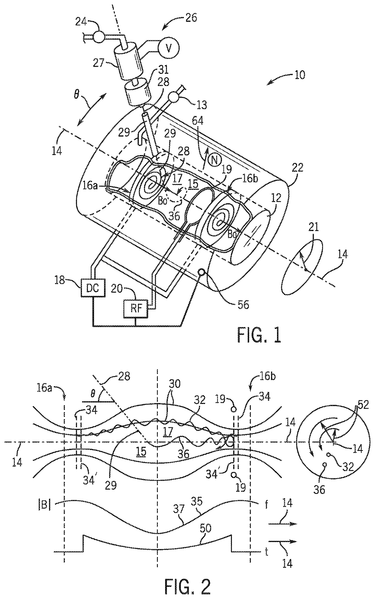
[0033]Referring now to FIG. 1, a high-energy plasma system 10 may provide a pressure vessel 12, for example, in the form of a sealed cylindrical shell of stainless steel or the like, extending along an axis 14 for receipt of a reaction gas, such as deuterium or tritium, through valve inlet assembly 13 from a pressure tank or the like (not shown).

[0034]First and second electromagnetic coils 16a and 16 may be positioned within the pressure vessel 12 near the opposed ends of the pressure vessel 12 to define a containment volume 17 therebetween having a magnetic containment field 15. The electromagnetic coils 16 are oriented and separated to form a Helmholtz pair aligned along axis 14 for establishing an axial Bo field therebetween. In one embodiment, the electromagnetic coils 16 may be pancake coils providing spirals about axis 14 powered by an external, controllable DC power supply 18 of the type understood in the art.

[0035]Positioned between the electromagnetic coils 16 but proximate...


PUM


Abstract

An apparatus for generating a highly energetic plasma employs a low-energy neutral beam injected into a magnetically contained mirror plasma to produce plasma ions boosted in energy to fusion levels by a coordinated radiofrequency field.

Description

STATEMENT REGARDING FEDERALLY SPONSORED RESEARCH OR DEVELOPMENT[0001]This invention was made with government support under DE-SC0002322 awarded by the US Department of Energy. The government has certain rights in the invention.BACKGROUND OF THE INVENTION[0002]The present invention relates to an apparatus for generating high-energy plasmas that can promote nuclear fusion, and in particular, to systems using magnetic mirror confinement and neutral beam injection, with additional radiofrequency power injection.[0003]High-temperature plasmas can be confined away from a physical container and avoiding damage to the container and possible plasma quenching, by a magnetic mirror confinement system. Such confinement systems may provide an axial magnetic field extending between two ends at which the magnetic flux lines converge. Plasma ions moving within this axial magnetic field spiral along the flux lines at the local cyclotron frequency and are “reflected” by an axial component of magnetic...

Claims


Application Information

Patent Timeline
Patent Type & Authority Patents(United States)
IPC IPC(8): H05H1/46G21B1/05G21B1/23
CPCH05H1/46G21B1/05G21B1/23H05H2001/4682H05H1/18Y02E30/10H05H2242/20
Inventor FOREST, CARY BRETTANDERSON, JAY KEITHWALLACE, JOHN PHILIPHARVEY, ROBERT W.PETROV, YURI V.
Owner WISCONSIN ALUMNI RES FOUND
Why Eureka
Try Eureka