Continuous steel casting method

a casting method and continuous steel technology, applied in the field of continuous steel casting methods, can solve the problems of insufficient technology disclosed in patent literature 1, the probability of a breakout due to insufficient thickness of the solidified shell significantly increases, and the average segregation spot diameter of the solidified structure of the strand is reduced, and the centerline segregation of solute elements is reduced

Active Publication Date: 2021-04-06
JFE STEEL CORP
View PDF26 Cites 0 Cited by
  • Summary
  • Abstract
  • Description
  • Claims
  • Application Information

AI Technical Summary

Benefits of technology

[0013]Specifically, the technology of utilizing, in combination, agitation caused by an electromagnetic force and soft reduction, as disclosed in Patent Literature 1, is a technology for reducing the flow of enriched molten steel to the thickness-wise middle portion of the strand and reducing the accumulation of the enriched molten steel therein. This is achieved by causing agitation by using electromagnetic force, thereby ensuring that the solidified structure of the thickness-wise middle portion of the strand is a fine equiaxed crystal structure and the flow resistance of the thickness-wise middle portion of the strand is increased. In addition, the technology is a technology for inhibiting the flow of enriched molten steel by performing soft reduction in the final stage of solidification to compensate for the solidification shrinkage, thereby reducing the flow driving force of the enriched molten steel. Accordingly, a high centerline segregation reducing effect can be expected. To meet the rigorous demands for quality, however, the technology disclosed in Patent Literature 1 is insufficient. It is necessary to further mitigate the centerline segregation that occurs within the equiaxed crystal structure of the strand.
[0016]Aspects of the present invention are directed toward solving these problems of the related art, and an object according to aspects of the present invention is to propose a continuous steel casting method that makes it possible to produce a strand in which centerline segregation is negligible and which, therefore, can meet the recent rigorous demands for the quality of steel products.
[0024]In accordance with aspects of the present invention, a static magnetic field is applied to a region of a strand, the region being a region where the solid fraction at a thickness-wise middle position of the strand is in a range of greater than 0 and 0.3 or less, the static magnetic field being applied in a direction orthogonal to the strand withdrawal direction at a predetermined strength for a predetermined length of time. Accordingly, thermal convection in the unsolidified layer within the strand is inhibited, which increases the temperature gradient of the unsolidified layer in a thickness direction of the strand. Consequently, the solidified structure of the thickness-wise middle portion of the strand is a columnar crystal structure. As a result, the solidification interface is uniform, and an average segregation spot diameter of the solidified structure of the strand is reduced. Hence, the following is achieved: a strand that is cast using a continuous casting machine has reduced centerline segregation of solute elements, such as carbon, phosphorus, sulfur, and manganese.

Problems solved by technology

Unfortunately, the technologies of the related art described above pose the following problems.
To meet the rigorous demands for quality, however, the technology disclosed in Patent Literature 1 is insufficient.
As a result, the solidified structure in the thickness-wise middle portion of the strand cannot be a columnar-crystallized structure.
In the technology, however, the degree of superheat of molten steel is set to be higher than or equal to 50° C., and as a result, the probability of a breakout due to an insufficient thickness of the solidified shell significantly increases.
To address this, it is necessary to reduce the strand withdrawal speed, and therefore productivity deteriorates.

Method used


Image

  • Continuous steel casting method
  • Continuous steel casting method

Examples


examples

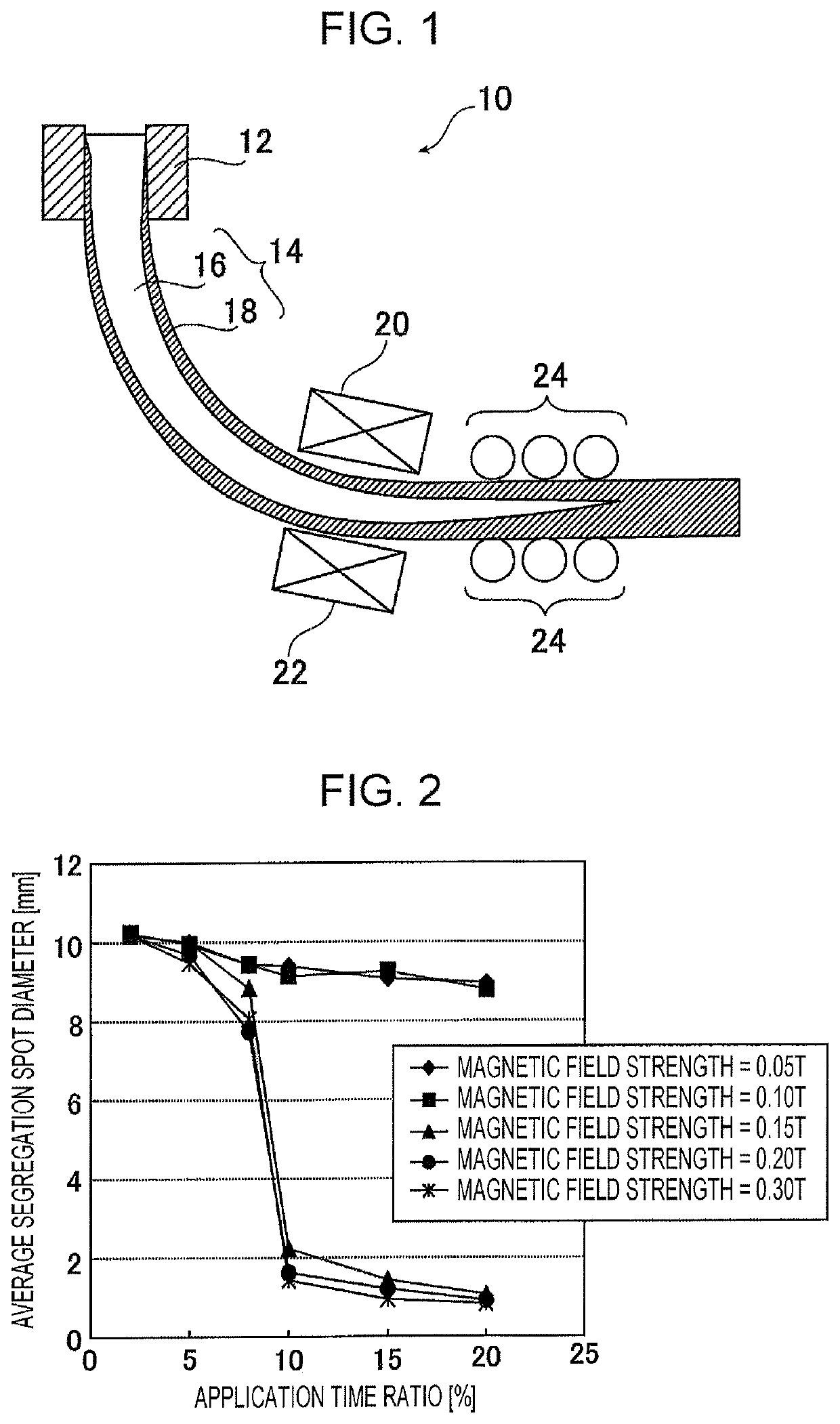
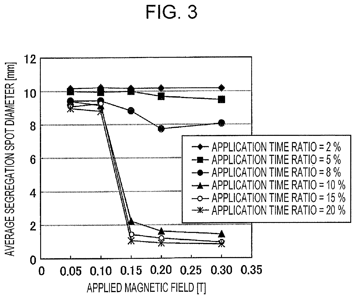
[0052]A strand was continuously cast by using a bloom continuous casting machine, which has the same configuration as the continuous casting machine illustrated in FIG. 1 and in which the line length of the continuous casting machine is 19.9 m and the radius of curvature thereof is 15 m. With the continuous casting machine, strands having a thickness of 250 mm and a width of 410 mm in terms of cross-sectional size can be cast. The components of the molten steel poured into the mold included the following: carbon, 0.7 mass %; silicon, 0.2 mass %; and manganese, 0.9 mass %. The strand withdrawal speed was 0.8 m / min, and the degree of superheat of molten steel (temperature of molten steel−liquidus temperature) in the tundish was 20° C.

[0053]Static magnetic field generation devices were installed at positions corresponding to a region where the solid fraction fs at the thickness-wise middle position of the strand is 0.24 to 0.30. Continuous casting was performed at various application t...


PUM

PropertyMeasurementUnit
magnetic fieldaaaaaaaaaa
temperatureaaaaaaaaaa
widthaaaaaaaaaa

Abstract

A continuous steel casting method includes producing a strand. The producing of the strand includes pouring molten steel into a mold of a continuous casting machine and withdrawing a solidified shell from the mold, the solidified shell being a solidified portion of the molten steel. The method includes applying a static magnetic field to at least a portion of a region of the strand, the strand being in the continuous casting machine, the region being a region where a solid fraction fs at a thickness-wise middle position of the strand is in a given range, the static magnetic field having a magnetic field strength of greater than or equal to 0.15 T and being in a direction orthogonal to a direction in which the strand is withdrawn, the static magnetic field being applied at an application time ratio of greater than or equal to 10%.

Description

CROSS REFERENCE TO RELATED APPLICATIONS[0001]This is the U.S. National Phase application of PCT / JP2017 / 013065, filed Mar. 29, 2017, the disclosure of this application being incorporated herein by reference in its entirety for all purposes.FIELD OF THE INVENTION[0002]The present invention relates to a continuous steel casting method that is effective for reducing centerline segregation present in strands produced by continuous casting.BACKGROUND OF THE INVENTION[0003]In continuous casting of steel, in the process in which the molten steel poured into a mold solidifies, solute elements, such as carbon (C), phosphorus (P), sulfur (S), and manganese (Mn), are driven away from the solidified shell-side toward the unsolidified layer-side. The solidified shell is the solid phase, and the unsolidified layer is the liquid phase. Such solute elements are concentrated in the unsolidified layer, which results in so-called segregation. The degree of the segregation is greatest at or near a thick...

Claims


Application Information

Patent Timeline
Patent Type & Authority Patents(United States)
IPC IPC(8): B22D11/20B22D27/02
CPCB22D11/207B22D27/02B22D11/122B22D11/205B22D11/1287B21D11/20
Inventor ODAGAKI, TOMOYAARAMAKI, NORICHIKAMIKI, YUJIKIKUCHI, NAOKI
Owner JFE STEEL CORP
Why Eureka
Try Eureka