
Electrocatalytic process for carbon dioxide conversion

a carbon dioxide and electrocatalytic technology, applied in the field of electrocatalytic process for carbon dioxide conversion, can solve the problems of preventing efficient conversion of carbon dioxide into energy-bearing products, lack of catalysts with sufficient activity at low overpotential and high electron conversion efficiency, and low rate of catalytic reaction,

Active Publication Date: 2021-04-13
DIOXIDE MATERIALS
View PDF230 Cites 5 Cited by
  • Summary
  • Abstract
  • Description
  • Claims
  • Application Information

AI Technical Summary

Benefits of technology

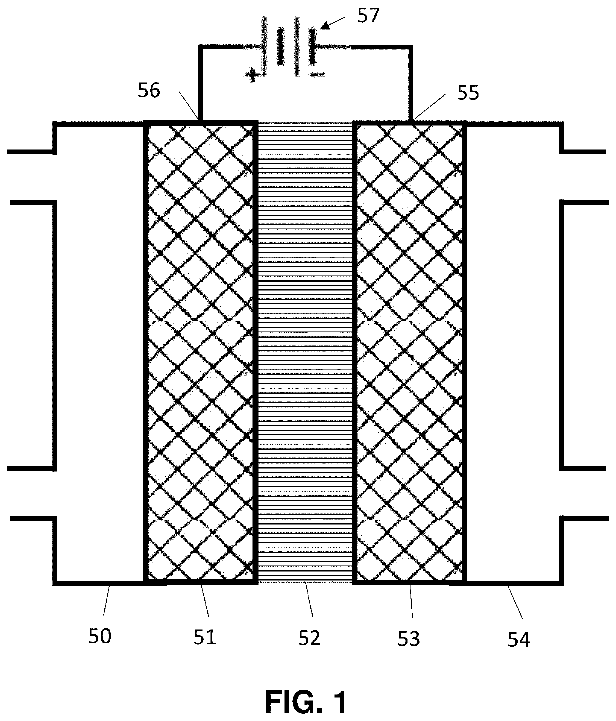
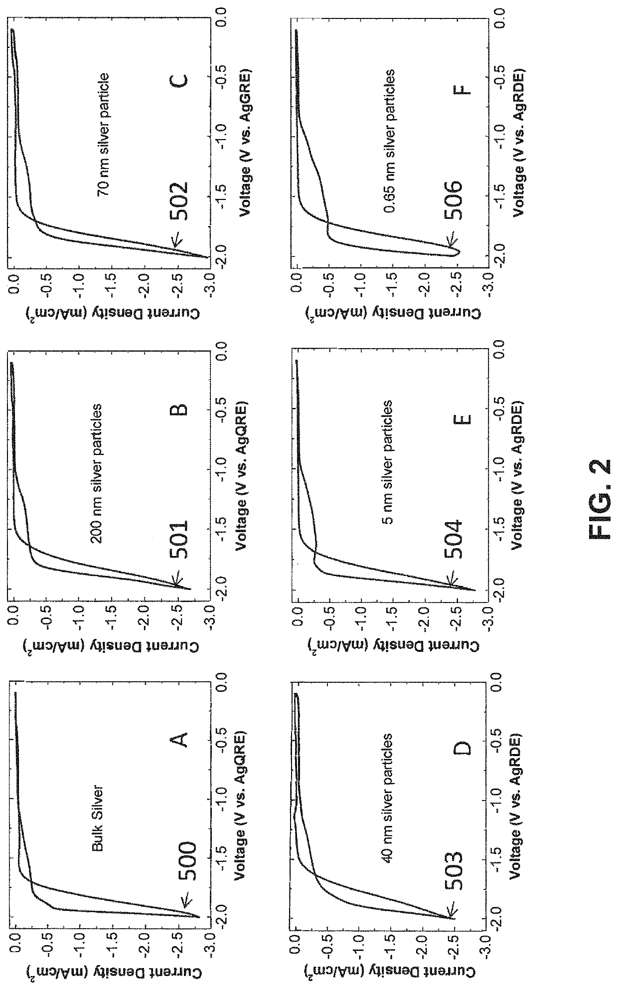
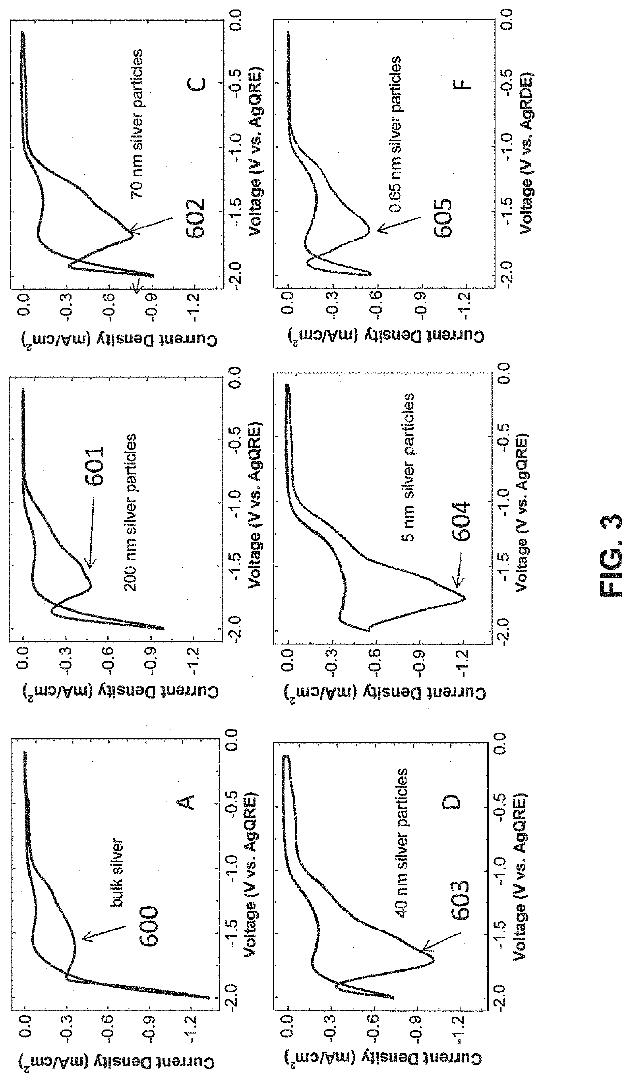
The process uses a new catalyst combination that solves problems such as low rates, high overpotentials, and low electron conversion efficiencies. The catalyst is made up of small particles with an average size of 0.6 nm to 100 nm, and a helper polymer containing positively charged groups. This catalyst combination is useful in electrochemical cells for converting CO2 to various products.

Problems solved by technology

Still, according to Bell (A. Bell. Ed, Basic Research Needs, Catalysis For Energy, U.S. Department of Energy Report PNNL17712, 2008) (“the Bell Report”), “The major obstacle preventing efficient conversion of carbon dioxide into energy-bearing products is the lack of catalyst” with sufficient activity at low overpotentials and high electron conversion efficiencies.
A second disadvantage of many of the catalysts is that they also have low electron conversion efficiency.
However, the catalysts disclosed in these patent applications showed a lower activity than was desired.
At present, these sensors require over 1-5 watts of power, which is too high for portable sensing applications.

Method used


Image

  • Electrocatalytic process for carbon dioxide conversion
  • Electrocatalytic process for carbon dioxide conversion
  • Electrocatalytic process for carbon dioxide conversion

Examples


example 1

lid Polymers as Helper Catalysts

[0128]The objective of this example is to show that polymers containing imidazoliums can be Helper Catalysts.

[0129]A copolymer, which is designated here as PSMIM (Cl), was prepared following the synthetic route in U.S. Pat. No. 9,370,773. “PSMIM” refers to a co-polymer of polystyrene and poly 1-(p-vinylbenzyl)-3-methyl-imidazolium:

[0130]

where X−is an anion, m>0 and n>0.

[0131]The inhibitor-free styrene was prepared by passing styrene (Sigma-Aldrich) through the tert-butylcatechol (TBC) inhibitor remover (Sigma-Aldrich 311340). In general, 40 ml of remover is sufficient to yield 50 ml of clear, inhibitor free styrene. Inhibitor TBC in 4-vinylbenzyl chloride (4-VBC) was removed by the same inhibitor remover in a similar fashion.

[0132]Poly(4-vinylbenzyl chloride-co-styrene) was then synthesized by heating a solution of inhibitor-free styrene (Sigma-Aldrich) (36.139 g, 350 mmol) and 4-vinylbenzyl chloride (Sigma-Aldrich) (29.7272 g, 190 mmol) in chlorobenz...

example 2

[0148]Example 1 used a single cell, but commercial designs will use a stack 300 where multiple cells are interconnected as illustrated in FIG. 6. The stack consists of a number of cells 301, 302, 303 and 304. Each cell has an anode 311, 312, 313 and 314, respectively, a cathode 321, 322, 323 and 324, respectively, and an ion-conducting membrane 331, 332, 333 and 334, respectively, interposed between the anode and the cathode. There are electrical connections 340, 341, 342 between (i) cathode 321 and anode 312, (ii) cathode 322 and anode 313, and (iii) cathode 323 and anode 314. Electrical potential is provided between anode 311 and cathode 324.

[0149]The figure only shows one example. There can be between 2 and 1000 cells in the stack.

[0150]Multiple arrangements of power are possible. In one case, power is provided to the ends of the stack. In a second case, power is provided to individual sections of the stack so that there is a source of potential between the cathode of one cell in...


PUM

PropertyMeasurementUnit
sizeaaaaaaaaaa
sizeaaaaaaaaaa
particle sizeaaaaaaaaaa

Abstract

An electrocatalytic device for carbon dioxide conversion includes an electrochemical stack comprising a series of cells with a cathode with a Catalytically Active Element metal in the form of supported or unsupported particles or flakes with an average size between 0.6 nm and 100 nm. The reaction products comprise at least one of CO, HCO−, H2CO, (HCOO)−, HCOOH, CH3OH, CH4, C2H4, CH3CH2OH, CH3COO−, CH3COOH, C2H6, (COOH)2, (COO−)2, and CF3COOH.

Description

CROSS-REFERENCE TO RELATED APPLICATIONS[0001]This application is a continuation-in-part of U.S. patent application Ser. No. 15 / 724,933 filed on Oct. 4, 2017 (scheduled to issue as U.S. Pat. No. 10,173,169 on Jan. 8, 2019), entitled “Electrocatalytic Process for Carbon Dioxide Conversion”. The '933 application is, in turn, a continuation-in-part of U.S. patent application Ser. No. 15 / 400,712 filed on Jan. 6, 2017 (now U.S. Pat. No. 9,815,021 issued on Nov. 14, 2017), also entitled “Electrocatalytic Process for Carbon Dioxide Conversion”. The '712 application is, in turn, a continuation-in-part of U.S. patent application Ser. No. 14 / 684,145 filed on Apr. 10, 2015 (now U.S. Pat. No. 9,555,367 issued Jan. 31, 2017), also entitled “Electrocatalytic Process for Carbon Dioxide Conversion”. The '712 application is also a continuation-in-part of U.S. patent application Ser. No. 15 / 158,227 filed on May 18, 2016 (now U.S. Pat. No. 9,945,040 issued on Apr. 17, 2018), entitled “Catalyst Layers a...

Claims


Application Information

Patent Timeline
Patent Type & Authority Patents(United States)
IPC IPC(8): B01J37/34C25B9/40C25B13/08C25B1/00C25B15/08C25B11/04C07C1/12C01B32/40C25B3/25C25B9/23B01J21/00B01J23/00B01J25/00B01J29/00B01J31/00
CPCC25B9/40C01B32/40C07C1/12C25B1/00C25B3/25C25B9/23C25B11/04C25B13/08C25B15/08Y02P30/20Y02P30/40
Inventor MASEL, RICHARD I.
Owner DIOXIDE MATERIALS
Learn More