Method of operating a secondary-electron multiplier in the ion detector of a mass spectrometer

a mass spectrometer and secondary electron technology, applied in the field of electronic incorporation of secondary electron multipliers, can solve the problems of insufficient pulse current of secondary electron generated by a single ion, and the noise of operating a preamplifier in a vacuum is particularly low, so as to improve the signal-to-noise ratio at the input of the digitizing unit, prolong the service life, and reduce the noise level

Active Publication Date: 2021-06-29
BRUKER DALTONIK GMBH & CO KG
View PDF17 Cites 0 Cited by
  • Summary
  • Abstract
  • Description
  • Claims
  • Application Information

AI Technical Summary

Benefits of technology

[0023]The inventors recognized that the signal-to-noise ratio at the input of the digitizing unit can be improved by amplifying the output signal of the SEM with a sufficiently low noise level by means of a preamplifier located close to the SEM, preferably even in the vacuum system of the mass spectrometer, or at least on the housing of the vacuum system, (e.g. flange-mounted there, close to the detector), and by operating the SEM at a correspondingly lower operating voltage so that the service life of the SEM is prolonged many times over. The preamplifier must, however, operate at a high enough speed so as not to distort the electron current pulses. Preamplifiers of this type are commercially available, see for example the TA2400 model from FAST ComTech GmbH (Oberhaching, Germany). If required, the preamplifier must also be designed so that it can be operated in a vacuum. Operating a preamplifier in a vacuum produces particularly low noise.
[0024]In various embodiments, the amplification of the secondary-electron multiplier can be set to be less than 105, preferably less than 2×10⁴, secondary electrons per impinging ion. This measure significantly reduces the energy input produced by the electron avalanche, which usually changes the surface coatings of secondary-electron multipliers, and thus prevents aging processes or at least slows them down.
[0025]In various embodiments, the low-noise amplification can be achieved by mounting the preamplifier close to the secondary-electron multiplier in the vacuum system of the mass spectrometer, or at least on the housing of the vacuum system (e.g. flange-mounted there, close to the detector). The low-noise amplification is preferably achieved by mounting the preamplifier less than 40 centimeters, particularly less than 30 centimeters, from the secondary-electron multiplier. A short signal line offers significantly less opportunity for external interferences to introduce noise into a signal transmission. The low-noise characteristic of the preamplifier can be improved by cooling, for example with the aid of a Peltier element or other suitable cooling element.
[0026]The patent application laid open to inspection DE 10 2008 064 246 A1 (Korea Basic Science Institute; corresponding to US 2009 / 0166533 A1) describes a Fourier transform ion cyclotron resonance mass spectrometer where a preamplifier is installed in a vacuum chamber as close as possible to an ion cyclotron resonance cell. The thermal noise generated in the preamplifier is minimized with the aid of a cryo-cooling system in order to improve the signal-to-noise ratio of ion detection signals so that an ultra-small quantity of a sample can be analyzed. Ion cyclotron resonance mass spectrometers operate with image charge transients of ions excited on orbits in the magnetic field of the cell, however, and require no signal amplification by means of secondary-electron multipliers, which is the reason why their operation and aspects of aging play no part in the disclosure of DE 10 2008 064 246 A1.

Problems solved by technology

However, at a low operating voltage, the pulse current of secondary electrons generated by a single ion is not sufficient to produce a digital signal which clearly stands out from the noise and can be unambiguously identified at the input of the digitizing unit.
Operating a preamplifier in a vacuum produces particularly low noise.

Method used


Image

  • Method of operating a secondary-electron multiplier in the ion detector of a mass spectrometer
  • Method of operating a secondary-electron multiplier in the ion detector of a mass spectrometer
  • Method of operating a secondary-electron multiplier in the ion detector of a mass spectrometer

Examples


Embodiment Construction

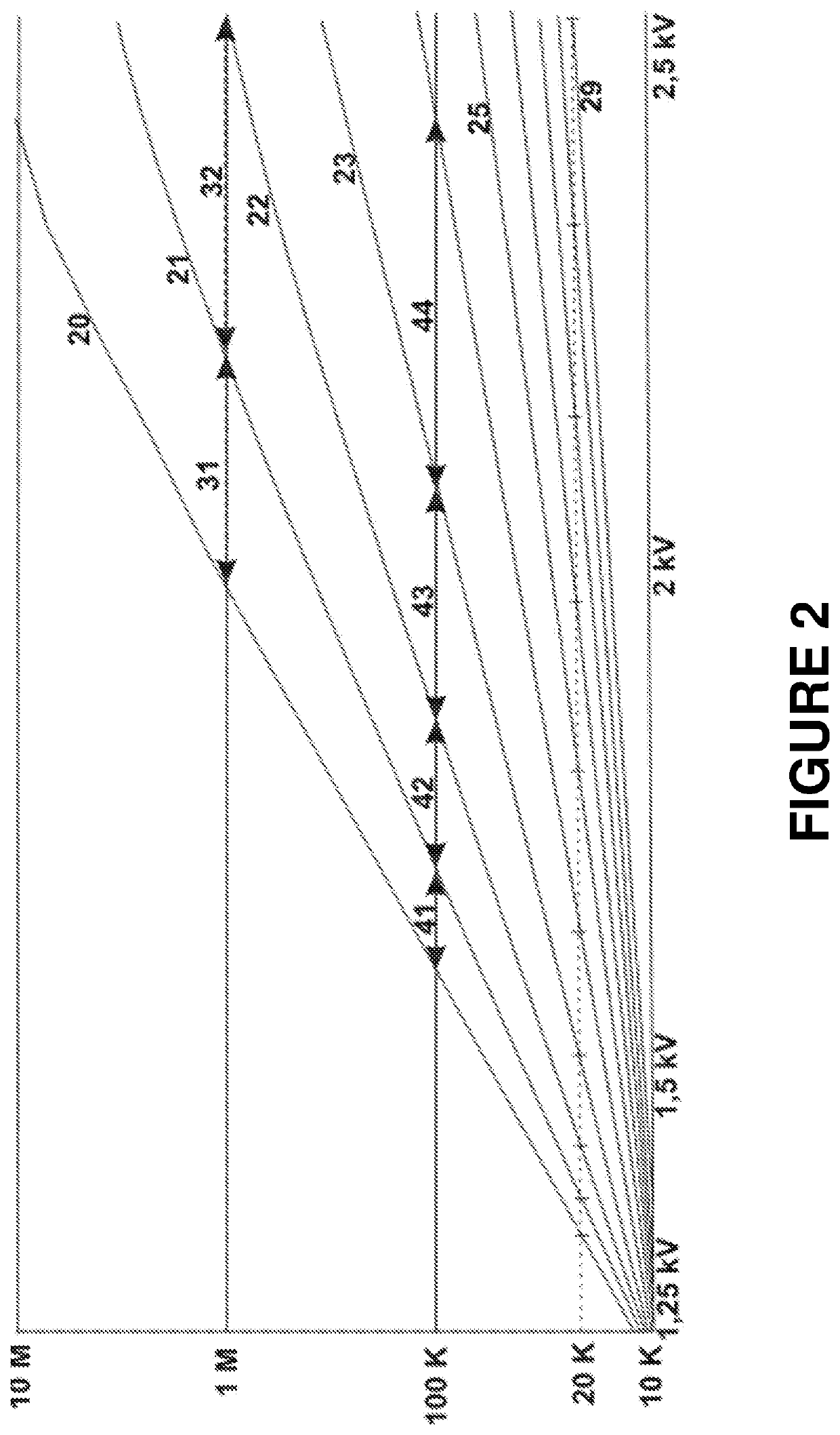
[0037]FIG. 2 is a theoretical representation, supported by measurements, of the group of characteristic curves (20) to (29) for the aging of a multiplier. The graph shows how each characteristic curve changes after specific operating periods of the same duration, for example after a period of around 100 operating hours in each case. The representation is based on two observations: (a) The aging occurs faster, the higher the amplification at which the SEM is operated. It is highly probable that this is because the greater number of secondary electrons which impinge at the end of the SEM causes a greater change in the work function of the active surface. (b) The SEM ages faster, the higher the operating voltage which must be set for a given amplification. This is probably because the energy of the impinging electrons is higher. A higher electron density and a higher electron energy accelerate the damage to the active surfaces, so lower yields of secondary electrons are achieved. If th...


PUM


Abstract

The disclosure relates to a method of operating a secondary-electron multiplier in the ion detector of a mass spectrometer so as to prolong the service life, wherein the secondary-electron multiplier is supplied with an operating voltage in such a way that an amplification of less than 106 secondary electrons per impinging ion results, while the output current of the secondary-electron multiplier is amplified using an electronic preamplifier mounted close to the secondary-electron multiplier with such a low noise level that the current pulses of individual ions impinging on the ion detector are detected above the noise at the input of a digitizing unit. Further disclosed are the use of the methods for imaging mass spectrometric analysis of a thin tissue section or mass spectrometric high-throughput analysis / massive-parallel analysis, and a time-of-flight mass spectrometer whose control unit is programmed to execute such methods.

Description

BACKGROUND OF THE INVENTIONField of the Invention[0001]The invention relates to the electronic incorporation of secondary-electron multipliers (SEM) in ion detectors of mass spectrometers.Description of the Related Art[0002]Several types of windowless secondary-electron multipliers (often called “multipliers” for short) can be used in mass spectrometers to measure very low ion currents. What they all have in common is that they age when operated in the vacuum of the mass spectrometer. The amplifications of commercially available multipliers can be adjusted over a wide range, in the extreme case between 104 and 108 (typically 106), by changing the operating voltage, although operating the multiplier at high voltages causes them to age very quickly. According to current thinking, aging occurs because the coatings on the dynodes are changed by the electron avalanches, and this increases the work function of the specially conditioned surfaces and reduces the yield of secondary electrons...

Claims


Application Information

Patent Timeline
Patent Type & Authority Patents(United States)
IPC IPC(8): H01J49/02H01J49/40H01J49/00
CPCH01J49/022H01J49/0031H01J49/025H01J49/40H01J49/0009H01J49/08
Inventor BÖHM, SEBASTIANHAASE, ANDREASHÖHNDORF, JENS
Owner BRUKER DALTONIK GMBH & CO KG
Why Eureka
Try Eureka