
Composite particles having hydrophilic and hydrophobic surface coatings

a technology of surface coating and composite particles, applied in the field of composite particles, can solve the problems of limited use of composite particles known so far, damage to the surface of many composite particles, and detachment of pigment particles, etc., and achieve the effect of reducing the proportion of expensive binders, such as resin, and good dispersibility

Active Publication Date: 2021-09-07
GEBR DORFNER GMBH & CO KAOLIN UND KRISTALLQUARZSAND WERKE
View PDF14 Cites 0 Cited by
  • Summary
  • Abstract
  • Description
  • Claims
  • Application Information

AI Technical Summary

Benefits of technology

The present invention relates to a new composite particle that has a unique surface coating that makes it easy to disperse in a synthetic resin matrix. The composite particle has a carrier particle made of quartz and layered silicate, with a hydrophilic region and a hydrophobic region on the surface. The hydrophilic region consists of a soluble glass coating, which helps in dispersibility and also prevents the composite particle from floating in the resin. The composite particle also has a clearly silvery gleaming metallic effect when used in a synthetic resin matrix, which makes it ideal for use as an effect particle. The surface coating can be adapted to the resin color to prevent discoloration. The technical effects of this invention are improved dispersibility, high shear force resistance, and a clear sparkling effect without color shifting or greying of the background.

Problems solved by technology

However, the use of composite particles known so far is limited.
In particular, if the intention is to embed the composite particles in a matrix, a person skilled in the art is restricted in his choice of surface coating, because in addition to ensuring the desired characteristics, he also has to ensure adequate dispersibility in the synthetic resin matrix.
Furthermore, during the effect of high shear forces, at least the surface of many composite particles is damaged, so that, for example, pigment particles become detached and the colour no longer corresponds to the desired colour shade following the exposure of the particles to the shear forces.

Method used


Image

  • Composite particles having hydrophilic and hydrophobic surface coatings

Examples


example

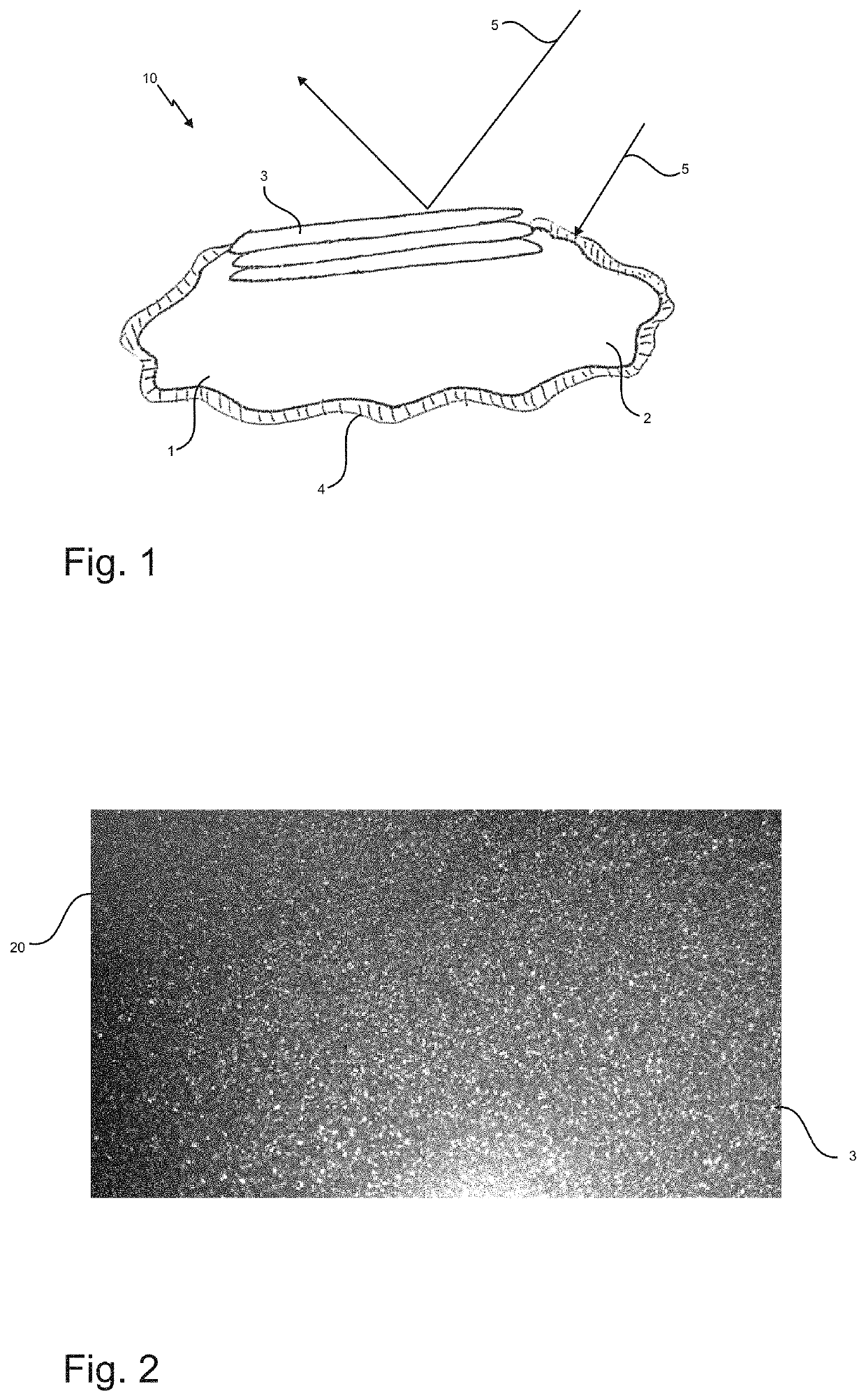
[0052]Mixtures based on coloured quartz are provided for the production of a composite material, as shown by way of example in FIG. 2, which can be used to produce kitchen sinks, for example. Due to the high shear resistance of the composite particle, on the one hand the high shear energies of the compulsory mixer can be withstood, and on the other hand the coated particles are not suctioned away by the dust extraction units due to the reinforcing coating and to the greater weight resulting therefrom. The faultless processibility means that the customer can be provided with complete mixtures. These mixtures can be specifically processed in a casting machine, without being destroyed in the mixing screw.

[0053]To produce a composite particle of this type, the raw material is introduced into a compulsory mixer. In a dry state, 1 mass % of a silver-coloured pigment is added and this is mixed into the raw material for one minute. Thereafter, 3 mass % of a sodium soluble glass are added an...


PUM

PropertyMeasurementUnit
grain sizeaaaaaaaaaa

Abstract

The invention relates to composite particles, comprising a carrier particle and an at least partial surface coating, the carrier particle comprising a quartz and a layered silicate and the surface of the composite particle having at least one hydrophilic region and at least one hydrophobic region. The invention also relates to a method for producing composite particles, comprising the steps:a) providing carrier particles, comprising a quartz and a layered silicate,b) introducing the carrier particles into a mixing device,c) charging the carrier particles with a coating composition,d) coating the carrier particles with the coating composition by mixing the carrier particles with the coating composition, with the introduction of shear energy,e) subjecting the coated carrier particles to temperature.In addition, the invention relates to a mineral cast part or to a composite workpiece which comprises the above-described composite particles.

Description

[0001]This application claims priority to German Patent Application No. 10 2017 111 515.3, filed May 26, 2017, the disclosure of which is incorporated herein by reference.TECHNICAL FIELD[0002]The present invention relates to composite particles comprising a carrier particle and an at least partial surface coating. The invention also relates to a method for producing composite particles. In addition, the invention relates to mineral cast parts or to composite workpieces which contain composite particles of this type.BACKGROUND OF THE INVENTION[0003]Composite particles are known from the prior art. Composite particles are usually composed of a carrier particle and a surface coating. The surface coating can provide the composite particle with a desired characteristic. Due to the carrier particle which is usually relatively inexpensive, particles can thus be provided which provide a desired material characteristic at a relatively low cost. For example, as a result of using appropriate s...

Claims


Application Information

Patent Timeline
Patent Type & Authority Patents(United States)
IPC IPC(8): C09C1/30C08K9/02C08K3/36C08K3/40C09C3/06C09C3/04
CPCC09C1/3054C08K3/36C08K3/40C08K9/02C09C3/043C09C3/063C01P2002/60C01P2004/84C08K2201/005
Inventor FLIERL, MICHAELSÜSS, MARCOKRÄUTER, REINHARD
Owner GEBR DORFNER GMBH & CO KAOLIN UND KRISTALLQUARZSAND WERKE
Learn More