Power system with internal combustion engine

Active Publication Date: 2021-10-12
NEW GENERATION ENGINES LLC
25 Cites 0 Cited by

AI-Extracted Technical Summary

Problems solved by technology

Further, oxygen may be accumulated in the tank during operation of the system to be used for purposes o...

Benefits of technology

[0004]The present invention is directed to a power system employing an internal combustion engine receiving a charge of fuel, concentrated oxygen and water. By using concentrated oxygen under pressure, all three components can be injected using multiple pulses for the combustion chamber charge. Such operation allows for greater control of oxygen-fuel ratios, ignition, burn rate, temperature and expansion of the charge. Complications resulting from constituents of air inducing air pollution can be diminished or avoided; and overall engine and vehicle efficiency can provide a substantial increase in...

Abstract

A power system including a variable volume combustion chamber for a two-stroke engine having a controlled exhaust port, a fuel injector to the combustion chamber, an oxygen injector to the combustion chamber and a water injector to the combustion chamber. The fuel, oxygen and water injectors controlled by a CPU provide repeated serial pulses of fuel, oxygen and water to complete a charge. An ignition chamber receives a compressed charge then ignited by a spark plug to pass through a restricted port to the main combustion chamber. A source of pressurized concentrated oxygen to the oxygen injector is in a closed air separator having a ceramic membrane of yttrium stabilized zirconia with a synthesized double perovskite nanofiber catalyst coating.

Application Domain

Electrical controlNon-fuel substance addition to fuel +4

Technology Topic

InjectorCombustion chamber +9

Image

  • Power system with internal combustion engine
  • Power system with internal combustion engine
  • Power system with internal combustion engine

Examples

  • Experimental program(1)

Example

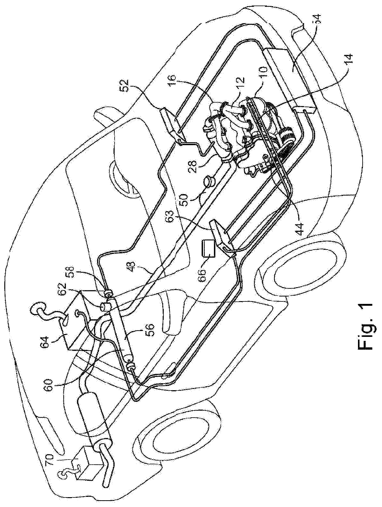
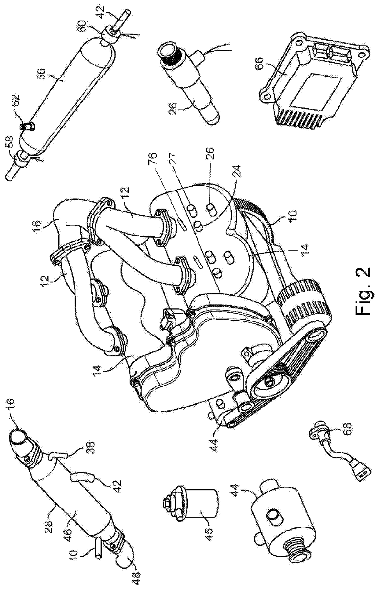
[0017]Turning in detail to the system illustrations, a power system is illustrated with power provided by an internal combustion engine 10 employing a cycle completed in two strokes. The engine 10 is illustrated to be a 90° V4 with a conventional cylinder block, crankshaft, pistons, connecting rods and rotary power output equipment. This is one example of use and configuration. Stationary and vehicular engines as well as single cylinder and other multi-cylinder engines are contemplated. In the illustrated example, a conventional belt-drive off the crankshaft is arranged to drive a cooling water pump, an alternator and an air compressor. A conventional timing belt drives an exhaust port cam and a water pump. Exhaust manifolds 12 extend directly out of heads 14 to accumulate exhaust in a collector 16 defining a single exhaust outlet.
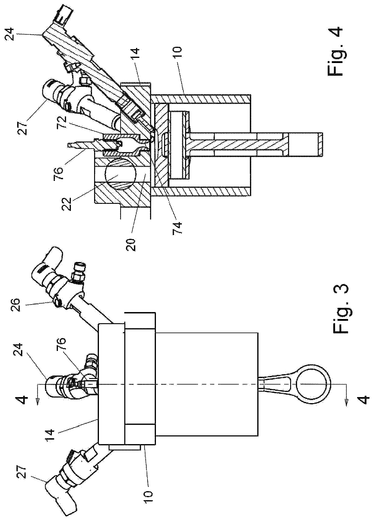
[0018]The arrangement of the heads 14 associated with the combustion chambers 18 is illustrated in FIGS. 3 and 4. Each variable volume combustion chamber 18 includes a portion of the head 14 having a controlled exhaust port 20 with a rotary valve 22 controlling the port. As the valve can allow flow in each direction, it may be rotated at half speed, with one rotation during two exhaust strokes. FIG. 4 illustrates a cross section through the port 20. A fuel injection system 24, an oxygen injection system 26 and a water injection system 27 extend to the combustion chamber 18 conveniently angularly displaced from one another about the head 14 of the chamber 18. The exact arrangement and orientation of the injectors of the injection systems 24, 26, 27 are to be empirically determined for each combustion chamber configuration.
[0019]The fuel injection system 24, whether injecting liquid or gaseous fuel, and oxygen injection system 26 are conventional products readily acquired, each most typically including a common rail distribution system with a solenoid injector 24, 26 at each combustion chamber electronically controlled by a CPU 66 that is timed by a crankshaft position sensor, a direct injection pump cam sensor and an exhaust valve cam shaft sensor. The water injection system 27 is similarly arranged and controlled. One or more of the injectors of the injection systems may be angled away from the centerline of the cylinder to generate mixing such as swirl and tumbling.
[0020]A source of concentrated oxygen includes an oxygen separator 28 illustrated in FIGS. 5 and 6. The oxygen separator 28 in the preferred embodiment is of a type including a pleated membrane 30 doped with perovskite or fluorites in a closed case 34. The closed case 34 has the membrane 30 located within the interior of the case defining a central air cavity 32 and an oxygen cavity 36 about the periphery. The membrane is a ceramic membrane of yttrium stabilized zirconia with a synthesized double perovskite nanofiber catalyst coating that extends the length between cavities allowing restricted flow therethrough. The case 32 also includes a waste outlet 40 also in communication with the first side of the membrane 30. Finally, the case 32 includes an oxygen outlet 42 which is in communication with the cavity 36 outwardly of the membrane 30.
[0021]The operating conditions of such oxygen separators typically include a differential pressure across a membrane of 10 to 90 bar and temperatures ranging from 500 to 700° C. To achieve such pressure differentials, the air inlet 38 is in communication with an air compressor 44. Such an air compressor 44 is shown to be belt-driven by the engine 10 to achieve operating pressures for the oxygen separator 28. A conventional water, oil and particle separator(s) 45 after the air compressor 44 protects the membrane 30. An additional pump after the oxygen outlet 42 may further increase the pressure drop across the membrane 30 and also act to boost pressure to the downstream components further discussed to provided pressurized oxygen to the engine injection system.
[0022]To achieve appropriate temperatures in the oxygen separator 28, a heat transfer association between the case 32 and the exhaust is used in addition to compressional heating by the air compressor 44 to provide a source of heat energy from the engine. In the preferred embodiment, a conduit 46 is arranged through the middle of the closed case 32. The conduit 46 is directly coupled with the exhaust collector 16 such that exhaust will flow through the closed case for heat transfer from the exhaust to the air flow into and through the ceramic membrane. The conduit 46 is also in communication with an exhaust pipe 48 to direct minimally restricted exhaust away from the equipment. The conduit 46 is preferably of thermally highly conductive material such as metal and may contain heat transfer enhancements such as fins or the like. More elaborate heat transfer devices may be used to increase heat transfer between the exhaust and the compressed air. Other heating sources may be used to accelerate and/or augment heating of the oxygen separator 28 or the incoming compressed air.
[0023]In considering various devices available in the art to be included here in the use of the phrase “oxygen separator”, air is considered to be principally made up of molecules of nitrogen and oxygen, accounting for approximately 99 mole percent, in a ratio of 78 N2 to 21 O2. The task may thus be considered one of separating oxygen and nitrogen to achieve a sufficient concentration of oxygen for volumetrically efficient engine operation. A useful concentration of oxygen may be obtained by a significant removal of nitrogen alone from air, whether the technology is principally considered to be separating oxygen from air or nitrogen from air. Thus, oxygen separators in addition to the oxygen separator 28 of the preferred embodiment are included here, devices which concentrate oxygen to attain sufficient volumetric efficiency to make oxygen injection practical and advantageous and to meet clean air standards without requiring exhaust catalytic conversion of oxides of nitrogen. The more limiting is the avoidance of oxides of nitrogen. An oxygen separator system which removes nitrogen from air to generate a gas stream therefrom that is at least 98 mole percent oxygen is sufficient to achieve these benefits.
[0024]Each of known membrane technologies, which include fiber membranes, hollow fiber membranes and solid electrolyte oxygen separation, and known pressure and vacuum swing technologies may be appropriated for oxygen separation in the source of concentrated oxygen to the engine. Such oxygen separators are preferably operated where most efficient, whether at high pressure and temperature or low. Generally, an air compressor 44 is to be used to properly charge the oxygen separator. Further boost to injection pressure may be accomplished with a gas compressor associated with the injector system. The choice of such known technologies and devices may depend on the type of vehicle or craft or stationary power source contemplated.
[0025]Returning to the preferred embodiment, to ensure that the appropriate working pressure in the case 32 is not exceeded, the waste outlet 40 is restricted by a conventional waste gate 50. The waste gate 50 is set at a predetermined pressure to maintain the closed case 32 in an efficient pressure range. Relief above a predetermined pressure through the waste gate 50 is permitted to flow to the exhaust pipe 48.
[0026]The source of pressurized concentrated oxygen from air provides a stream from the ceramic fiber membrane 30 through the oxygen outlet 42 which is at least 98 mole percent oxygen. The pressurized concentrated oxygen is shown in the preferred embodiment to first be directed to an intercooler 52 to cool the oxygen, increasing oxygen density. The intercooler 52 may be conveniently water cooled by a radiator 54 as may be available when the power system is used on a vehicle. Further gas pressure can also be obtained after the oxygen outlet 42 by a gas compressor which may be independent or a separate compressor component stage in the air compressor 44 (communication lines not shown) driven in either case directly or indirectly by the engine 10. For better efficiency, gas compression would appropriately be followed by gas cooling. The concentrated oxygen at a preferred pressure is then directed to an oxygen tank 56.
[0027]The oxygen tank 56 preferably has the capacity to maintain a sufficient volume of concentrated and pressurized oxygen to provide starting and warmup for the engine and ceramic fiber membrane 30 from a cold start. Additionally, the capacity of the oxygen tank 56 accommodates fluctuations in increased engine demand and variations in the output of the oxygen separator 28.
[0028]An inlet regulator 58 and an outlet regulator 60 are arranged at the inlet and outlet of the oxygen tank 56, respectively. The outlet regulator 60 maintains a constant pressure for discharging concentrated and pressurized oxygen to the oxygen injectors 26. The inlet regulator 58 prevents backflow toward the ceramic fiber membrane 30 and provides a maximum pressure signal if the oxygen tank becomes over pressurized. A primer valve 62 provides access to the oxygen tank 56 for additional charging. A further increase in density of the concentrated oxygen for volumetric efficiency may be additionally or alternatively provided by an intercooler 63 between the oxygen tank 56 and the engine 10. Such an intercooler 63 may be thermally coupled with the radiator 54 or otherwise cooled. The intercooler 63 may be paired with a compressor, again, independent or a separate compressor component stage in the air compressor 44 (communication lines not shown) driven in either case by the engine 10. Alternatively or additionally, refrigeration of the oxygen tank 56 may be employed toward the same end.
[0029]Fuel to be delivered to the fuel injectors 24 is maintained in an appropriate fuel tank 64. A low-pressure pump having conventional 50 to 60 psi capacity (not shown) is associated with the fuel tank 64. A higher-pressure tank and pump would be used for gaseous fuel. The fuel injection system is also conventional, most typically a common rail distribution system including a high-pressure direct injection fuel pump boost to 2900 psi. Conventional solinoid injectors 24 at each combustion chamber are fed by the distribution system and electronically controlled by the CPU 66 timed by a crankshaft position sensor 68, a direct injection pump cam sensor and an exhaust valve cam shaft sensor.
[0030]Water employs hardware, similar to that of liquid fuel, associated with a water tank 70 feeding the water injectors 27 controlled by the CPU 66. The water tank 70 may be charged like the fuel tank 64; or the water may be recovered from the products of combustion and charged water to the cylinders.
[0031]The exhaust valves 22 in the exhaust ports 20 are rotary valves controlled by a conventional valve train driven by a crankshaft. No intake valve is needed as no air is involve in the cylinder charge.
[0032]The cylinder head 14 further includes an ignition chamber 72 having a restricted port 74 between the ignition chamber 72 and the cylinder. The restriction is shown to be a venturi, causing increased mixing as oxygen and fuel are charged to the chamber and a dispersive effect on combusting gasses accelerated through the restriction with the venturi 74 at the outlet. A spark plug 76 extends into the chamber for ignition. A further spark plug (not shown) may also be mounted in the engine head 14 and extend directly into the combustion chamber 18 to augment ignition.
[0033]The operation of the power system is preferably controlled by the electronic control unit 66. Such units, commonly referred to as engine control modules, are commonly employed to regulate various vehicle engine operations. The CPU 66 can monitor pressures and temperatures throughout the system and may receive the overpressure signal from the inlet regulator 58 on the oxygen tank 56. Further, the CPU 66 may appropriately engage or disengage an electric clutch drive or drives on the air compressor 44 to maintain pressure in the oxygen tank 56 and elsewhere within appropriate boundaries. The CPU 66 further can monitor throttle input from a vehicle and modulate fuel, oxygen and water to the combustion chambers through conventional control of the injectors 24, 26, 27. This modulation, typically based on mapped fuel curves, provides control of engine power and at the same time achieve a final charge from the accumulated pulses maintaining an appropriate oxygen-fuel ratio charge through the power stroke. The CPU 66 can typically measure optimized performance of the engine and any associated vehicle. The crankshaft position sensor 68 is one such device providing input to the CPU 66 for engine control along with a direct injection pump cam sensor and an exhaust valve cam shaft sensor, determining injector timing and control.
[0034]Turning to operation of the two-stroke cycle, the fuel, oxygen and water injectors act serially in repeated pulses to charge the combustion chamber as controlled by the CPU 66 for timing and quantity. With regard to the combustion components, the CPU 66 controls the injectors to initiate a first serial injection pulse before top dead center. The intention is to achieve an acceptable total oxygen-fuel charge to the cylinder with each combustion stroke. The fuel and oxygen injectors operate through a series of pulses which provide controlled oxidation of the fuel over a period of time with both oxygen and fuel pulses terminating no earlier than the point of maximum crank leverage. In the current preferred embodiment, the point of maximum crank leverage is at 77° after TDC. Conditions of the burn suggest further advantage to extend charging beyond the maximum crank leverage to as late as 90° after TDC. The timing of and oxygen-fuel ratio between injections can be varied depending on the performance desired. Injection for a cooler and cleaner burn may require different timing and oxygen-fuel ratio than injection for maximum power. With completion of the fuel and oxygen injection in a given stroke, the accumulated ratio of oxygen-fuel injected should be at a stoichiometric or leaner oxygen-fuel ratio.
[0035]With a sufficiently lean ratio, the exhaust should only contain carbon dioxide, water, and potentially some remaining oxygen. If the concentrated oxygen is less than pure, unreactive components will also be present. The oxygen purity as to residual nitrogen is to be sufficient to not require catalytic removal of oxides of nitrogen to meet federal vehicle standards; and “concentrated oxygen” is defined for purposes here to mean that which will meet this requirement. A concentration of 98 mole percent oxygen in the stream to the injectors extracted from the air processed through the oxygen separator 28 is understood to meet this requirement.
[0036]Ignition is initiated using the ignition chamber 72 in the cylinder head. The initial pulse or pulses of the serial injections are injected before TDC in order to drive charge into the ignition chamber 72 as the piston moves toward the head. Full closure of the exhaust port 20 is tuned to occur soon enough that a first pulse of the serial injection will be forced under pressure into the ignition chamber 72. This initial charge may be comparatively rich. Once accomplished, the spark plug is timed to fire, discharging combusting gasses into the main combustion chamber, which may then be receiving subsequent leaner oxygen-fuel ratio pulses.
[0037]If liquid hydrocarbons are the fuel, they may be introduced under a conventional 2900 psi pressure. Fuel may be preconditioned through heating. Reference is made to U.S. Pat. No. 8,511,287 to Hofbauer et al., the disclosure of which is incorporated herein by reference. Ambient oxygen temperature prior to injection is most convenient. Refrigeration may also be employed to increase total efficiency. The oxygen injection is with the concentrated oxygen at 90 bar and at a temperature lowered from that generated by the prior compression.
[0038]Additionally, water is injected with the fuel and oxygen and this serial injecting of fuel, oxygen and water is done so repeatedly during the power stroke under the control of the CPU 66. Each engine design is unique and the conditions change as the engine warms, as engine speeds change and as power is demanded. All must be empirically tuned. Under some conditions, the initial serial injection may be fuel rich and water lean to initiate combustion while a later serial injection may be a leaner oxygen-fuel mix with more water to provide greater expansion and thermal control. An even later serial injection may increase oxygen with less water to complete combustion, for example. The amount of water is to be less than will quench or significantly retard the burn, otherwise resulting in unburned fuel in the exhaust. The appropriate amount of water may also vary with the temperature of the engine.
[0039]The exhaust valve 22 is mechanically coupled with the crankshaft of the engine. Spontaneous or induced ignition may impact injection and exhaust port timing. Adequate scavenging of exhaust is not understood to be an issue. In the preferred embodiment, the exhaust port 20 begins to open at 172° after TDC, is fully open at 199° after TDC. Opening of the exhaust port 20 may also begin when most advantageous to maximize scavenging with minimal impact to the power stroke. Full closure of the exhaust port 20 may occur somewhere within the range of 45° and 25° before TDC. Un-scavenged combusted gases can provide extra heat to assist ignition.
[0040]Thus, an improved, efficient and clean burning power system has been disclosed. While embodiments and applications of this invention have been shown and described, it would be apparent to those skilled in the art that many more modifications are possible without departing from the inventive concepts herein. The invention, therefore, is not to be restricted except in the spirit of the appended claims.

PUM

no PUM

Description & Claims & Application Information

We can also present the details of the Description, Claims and Application information to help users get a comprehensive understanding of the technical details of the patent, such as background art, summary of invention, brief description of drawings, description of embodiments, and other original content. On the other hand, users can also determine the specific scope of protection of the technology through the list of claims; as well as understand the changes in the life cycle of the technology with the presentation of the patent timeline. Login to view more.

Similar technology patents

Enhancing tire performance utilizing releasable elements

InactiveUS20110000733A1expand rangeincrease fuel economy
Owner:GM GLOBAL TECH OPERATIONS LLC

Control module for a vehicle

InactiveUS20110054769A1increase fuel economy
Owner:SEXTON PARTNERS

Exhaust gas recirculation control

ActiveUS20150033735A1reduce exhaust emissionincrease fuel economy
Owner:FORD GLOBAL TECH LLC

Method and system for variable displacement engine diagnostics

ActiveUS10487763B2increase fuel economy
Owner:FORD GLOBAL TECH LLC

Linear electric motor controller and system for providing linear control

InactiveUS7265516B2increase fuel economyreduce weight and size
Owner:2112376 ONTARIO

Classification and recommendation of technical efficacy words

  • increase fuel economy

Tire with tread having base layer comprised of diverse zoned rubber compositions

ActiveUS20120285590A1increase fuel economyhigh stiffness
Owner:THE GOODYEAR TIRE & RUBBER CO

Control module for a vehicle

InactiveUS20110054769A1increase fuel economy
Owner:SEXTON PARTNERS

Exhaust gas recirculation control

ActiveUS20150033735A1reduce exhaust emissionincrease fuel economy
Owner:FORD GLOBAL TECH LLC

Linear electric motor controller and system for providing linear control

InactiveUS7265516B2increase fuel economyreduce weight and size
Owner:2112376 ONTARIO

Enhancing tire performance utilizing releasable elements

InactiveUS20110000733A1expand rangeincrease fuel economy
Owner:GM GLOBAL TECH OPERATIONS LLC
Why Eureka
Try Eureka