Soft x-ray optics with improved filtering

a soft x-ray optic and filtering technology, applied in the field of xray optics, can solve the problems of contaminating soft x-ray based measurements, characterization difficulty, and lower energy radiation (e.g., euv, uv, visible, ir) to achieve the effect of preventing diffusion and increasing the lifetime of multi-layer optics without affecting optical performan

Active Publication Date: 2021-10-12
KLA CORP
View PDF75 Cites 2 Cited by
  • Summary
  • Abstract
  • Description
  • Claims
  • Application Information

AI Technical Summary

Benefits of technology

[0013]In one aspect, one or more optical elements of an x-ray based system include an integrated optical filter including one or more material layers that absorb radiation having energy outside the desired energy band. In general, the integrated filter improves the optical performance of an x-ray based system by suppressing reflectivity within infrared (IR), visible (vis), ultraviolet (UV), extreme ultraviolet (EUV) portions of the spectrum, or any other undesired wavelength region.
[0015]In a further aspect, an integrated optical filter includes one or more diffusion barrier layers to prevent degradation of the integrated optical filter by the external environment, prevent diffusion between the integrated optical filter and other material layers, or both. In many embodiments, a thin diffusion barrier layer effectively increases the lifetime of a multilayer optic without affecting its optical performance.

Problems solved by technology

As devices (e.g., logic and memory devices) move toward smaller nanometer-scale dimensions, characterization becomes more difficult.
Devices incorporating complex three-dimensional geometry and materials with diverse physical properties contribute to characterization difficulty.
However, lower energy radiation (e.g., EUV, UV, visible, IR) contaminates soft x-ray based measurements.
As a result, soft x-ray based systems employing traditional multilayer optic 10 suffer from EUV light contamination.
These extremely thin membranes, which are unsupported over a relatively large distance, are costly and extremely fragile.
This negatively impacts the reliability and practical utility of current soft x-ray based systems.

Method used


Image

  • Soft x-ray optics with improved filtering
  • Soft x-ray optics with improved filtering
  • Soft x-ray optics with improved filtering

Examples


Embodiment Construction

[0035]Reference will now be made in detail to background examples and some embodiments of the invention, examples of which are illustrated in the accompanying drawings.

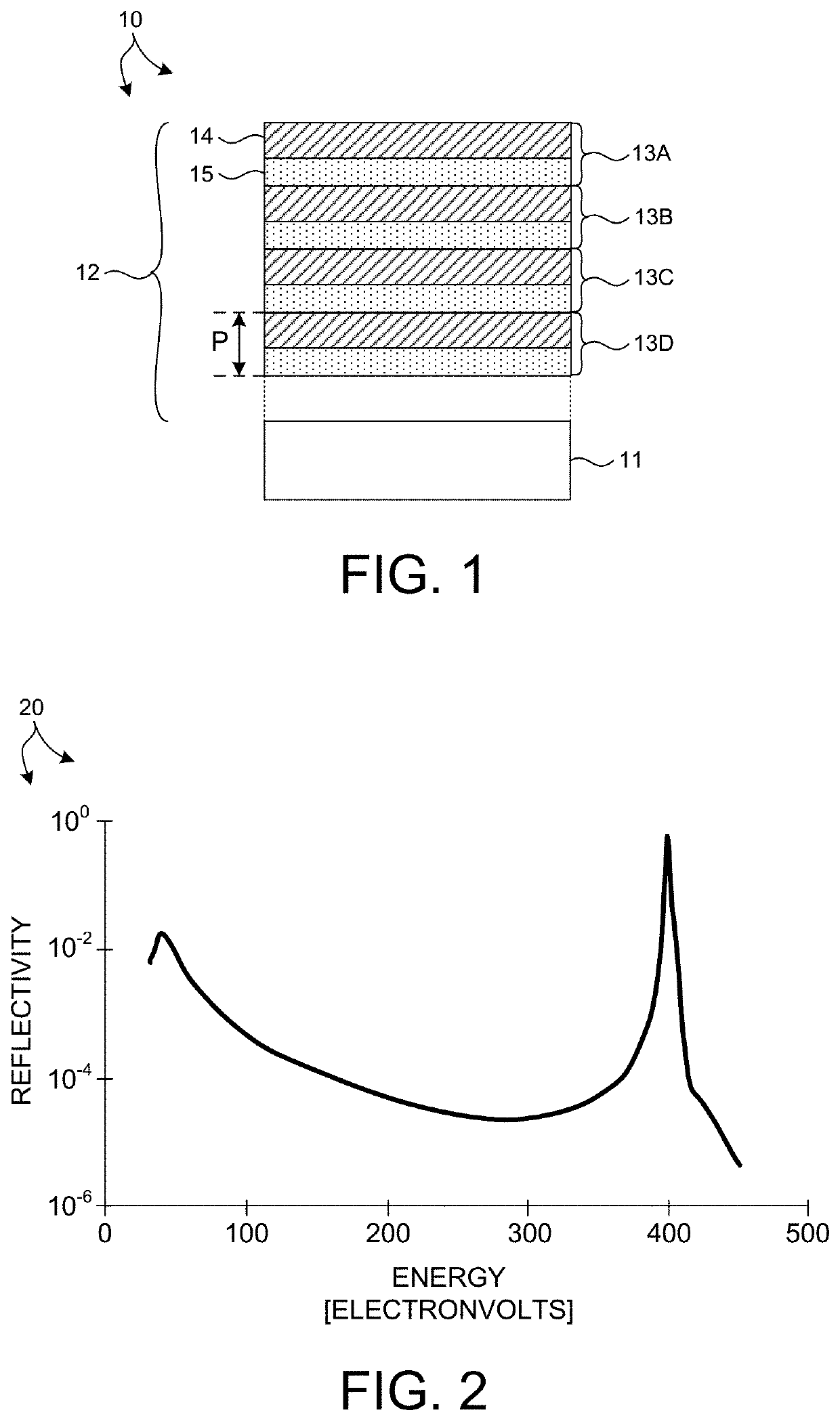
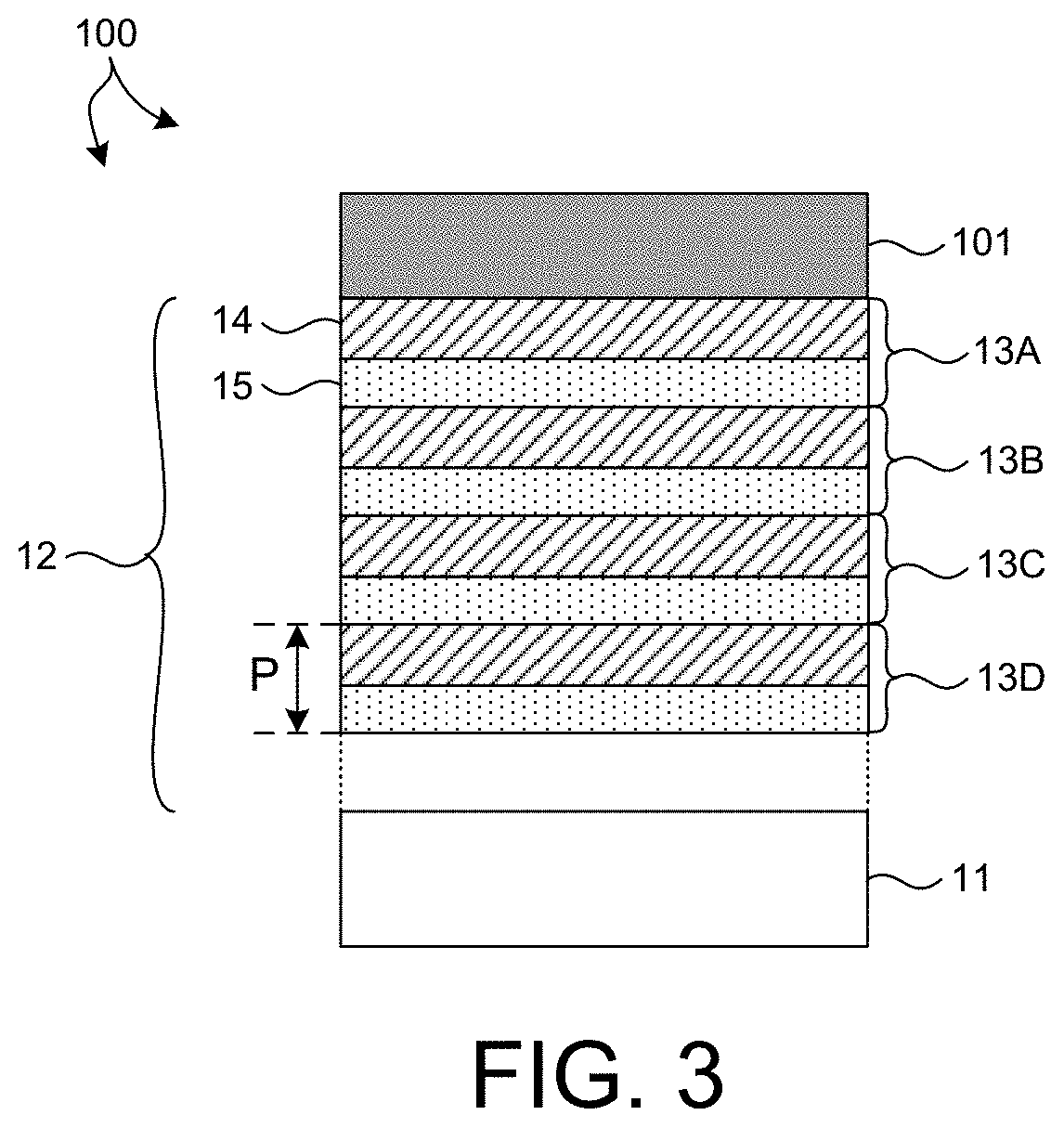
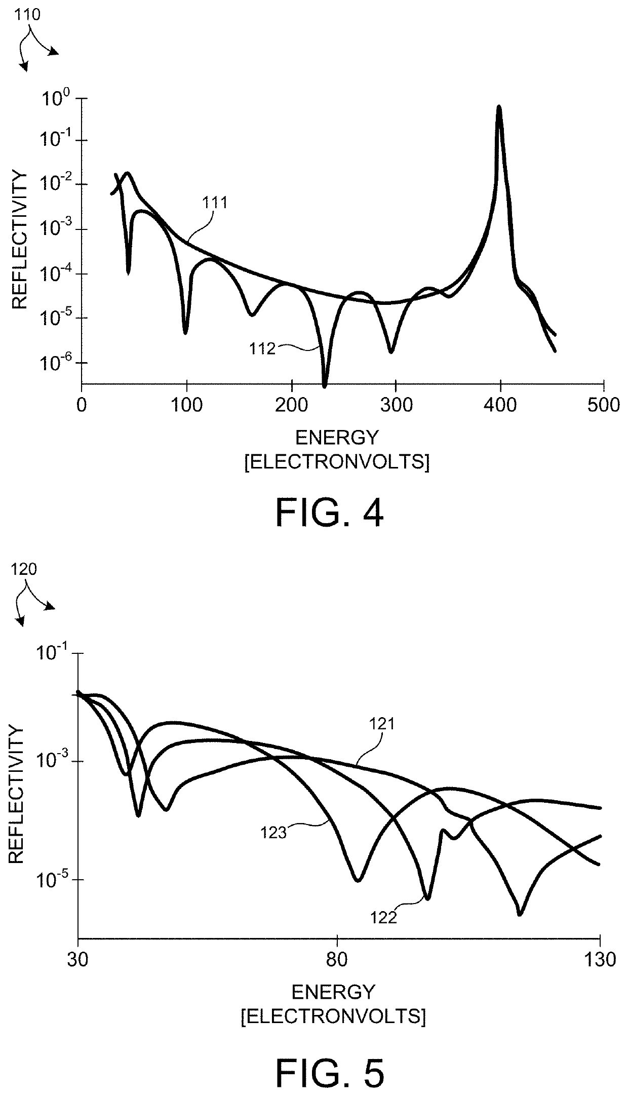
[0036]Optical elements that efficiently propagate x-ray radiation over a desired energy range and reject radiation outside the desired energy range are presented herein. In addition, x-ray based metrology systems including optical elements that efficiently propagate x-ray radiation over a desired energy range and reject radiation outside the desired energy range are also presented. In particular, broadband, soft x-ray based metrology systems employ optical elements that propagate broadband, soft x-ray radiation and reject wavelengths in the EUV, UV, visible, IR, or any combination thereof.

[0037]In one aspect, one or more optical elements of an x-ray based system include an integrated optical filter including one or more material layers that absorb radiation having energy below the desired energy band. In some embodime...


PUM

PropertyMeasurementUnit
photon energyaaaaaaaaaa
thicknessaaaaaaaaaa

Abstract

Optical elements that efficiently propagate x-ray radiation over a desired energy range and reject radiation outside the desired energy range are presented herein. In one aspect, one or more optical elements of an x-ray based system include an integrated optical filter including one or more material layers that absorb radiation having energy outside the desired energy band. In general, the integrated filter improves the optical performance of an x-ray based system by suppressing reflectivity within infrared (IR), visible (vis), ultraviolet (UV), extreme ultraviolet (EUV) portions of the spectrum, or any other undesired wavelength region. In a further aspect, one or more diffusion barrier layers prevent degradation of the integrated optical filter, prevent diffusion between the integrated optical filter and other material layers, or both. In some embodiments, the thickness of one or more material layers of an integrated optical filter vary over the spatial area of the filter.

Description

TECHNICAL FIELD[0001]The described embodiments relate to x-ray optics, and more particularly to thin film optical layers employed to filter out of band radiation in optical systems.BACKGROUND INFORMATION[0002]Semiconductor devices such as logic and memory devices are typically fabricated by a sequence of processing steps applied to a specimen. The various features and multiple structural levels of the semiconductor devices are formed by these processing steps. For example, lithography among others is one semiconductor fabrication process that involves generating a pattern on a semiconductor wafer. Additional examples of semiconductor fabrication processes include, but are not limited to, chemical-mechanical polishing, etch, deposition, and ion implantation. Multiple semiconductor devices may be fabricated on a single semiconductor wafer and then separated into individual semiconductor devices.[0003]Metrology processes are used at various steps during a semiconductor manufacturing pr...

Claims


Application Information

Patent Timeline
Patent Type & Authority Patents(United States)
IPC IPC(8): G01N23/20008G21K1/10G01N23/201G21K1/06
CPCG01N23/20008G01N23/201G21K1/062G21K1/10G01N2223/6116G01B15/02G01B15/08G01B2210/56G21K2201/067G01N2223/054G01N2223/1016G01N2223/313G01N2223/633G01N2223/6462
Inventor KUZNETSOV, ALEXANDERCHEN, BOXUEARTEMIEV, NIKOLAY
Owner KLA CORP
Why Eureka
Try Eureka