Noise suppressing assemblies

a shielding assembly and noise suppression technology, applied in the direction of transformers, chemistry apparatuses and processes, inductances, etc., can solve the problems of loss of transmission, excess heat generation, and lower efficiency and potential chances of electromagnetic interface, so as to improve power transmission efficiency, improve efficiency of power transmission, and fast wireless charging of mobile devices

Active Publication Date: 2021-11-30
NEOGRAF SOLUTIONS LLC
View PDF93 Cites 0 Cited by
  • Summary
  • Abstract
  • Description
  • Claims
  • Application Information

AI Technical Summary

Benefits of technology

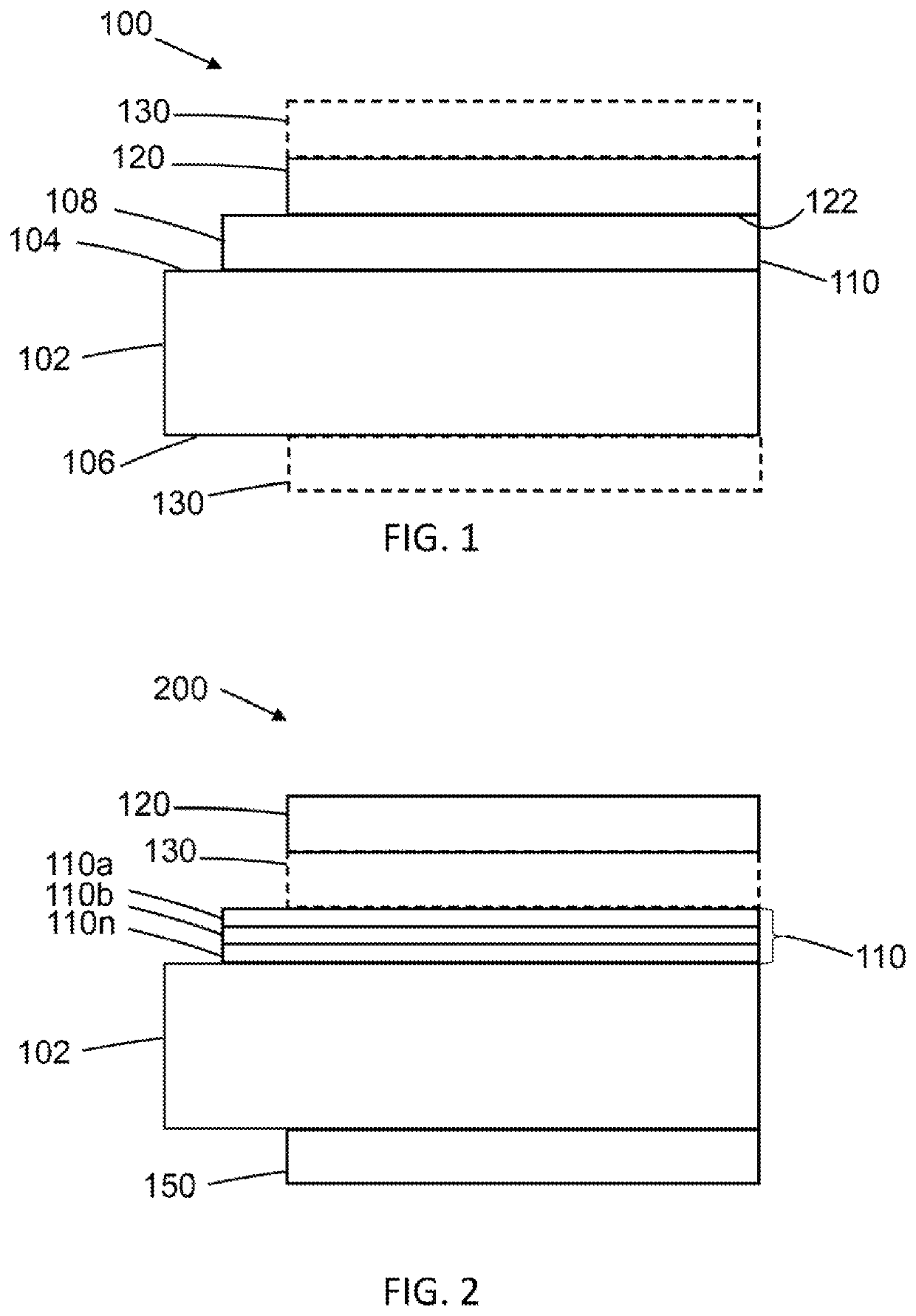
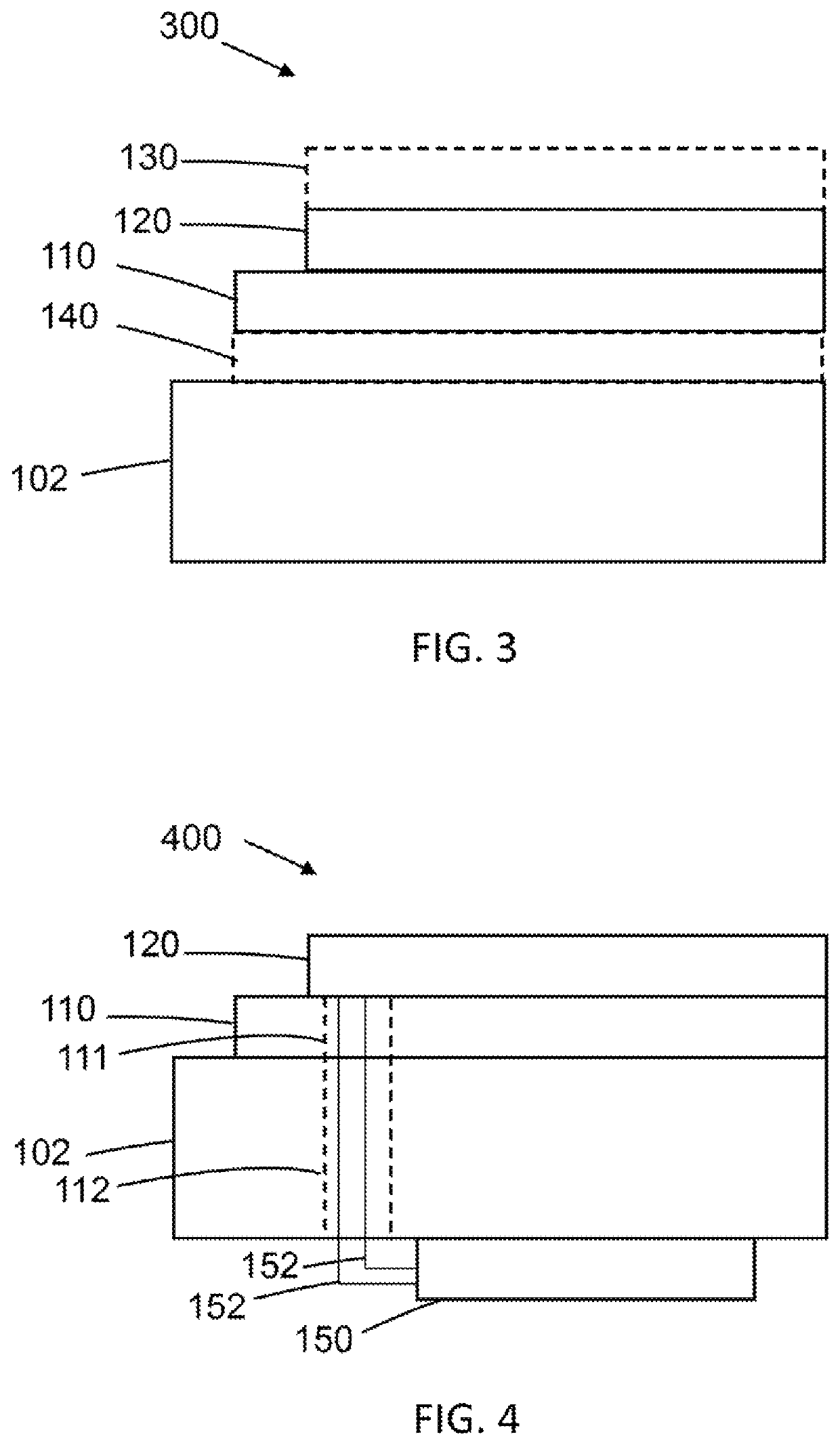
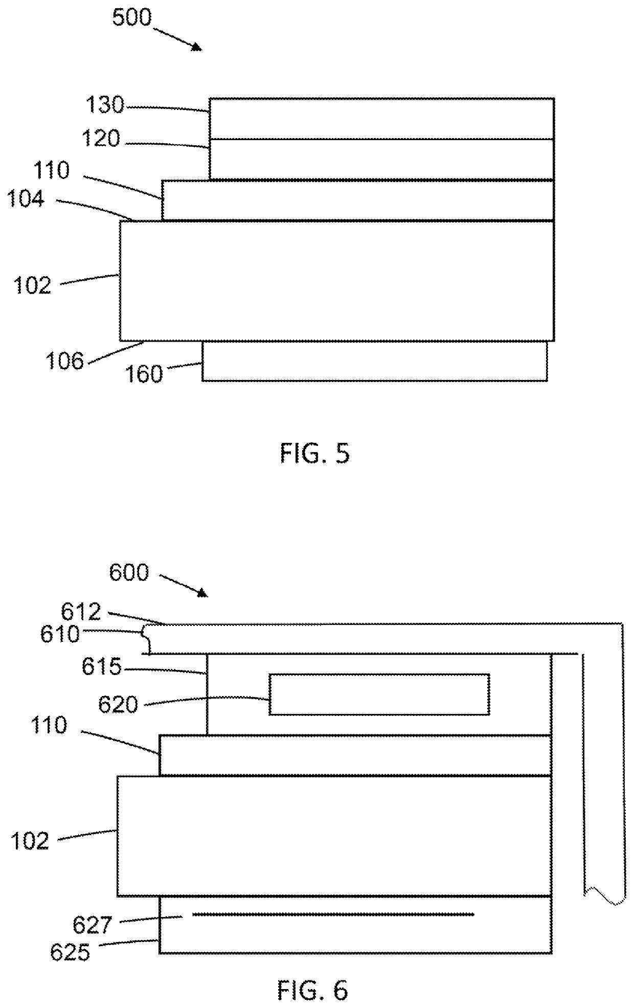
[0004]An embodiment described herein includes an assembly that may have multi-functionality of any combination of heat spreading, absorption of stray radiation, signal focusing, and shielding. An embodiment of the assembly has a thickness of no more than 500 microns. The assembly may include a heat spreading layer comprised of at least one sheet of a compressed particles of exfoliated graphite, graphitized polymers and combinations thereof. The heat spreading layer may have an in-plane thermal conductivity of at least about 300 W / mK up to about 2,100 W / mK. The thickness of the heat spreading layer may range from 17 microns up to about 250 microns. The assembly may also include a magnetic layer, which may provide the benefits of magnetic flux management and / or stray radiation absorption. The magnetic layer may have a thickness of no more than about 300 microns. In an embodiment, the magnetic layer may comprise no more than sixty percent by weight (60% pbw) of iron, no more than sixty percent by weight (60% pbw) of nickel, no more than fifteen percent by weight (15% pbw) of binder and no more than twenty percent by weight (20% pbw) for the combination of elements of chromium, silicon and molybdenum. Lastly, the assembly may include an optional plastic coating on one or both of the exterior surfaces of the assembly. This assembly may be used to enable fast wireless charging of mobile devices by efficiently focusing magnetic flux for better power transmission efficiency, as well as managing noise generation. The assembly may be disposed in a device adjacent the induction coil for wireless charging. Such coil is typically proximate a back or intended bottom surface of the device.
[0007]Articles described herein can also provide broadband electromagnetic shielding. The hybrid solution has a resilient structure and efficient low frequency shielding due to electrically conductive mesh and high frequency shielding and heat spreading due to graphite composite that results in a broadband (KHz-100 GHz) electromagnetic shielding solution in conjunction with thermal management.

Problems solved by technology

In an ideal situation, all the transmitted power from the Tx is received by the Rx resulting in perfect power transfer, however there are usually losses in the transmission due to various factors including coupling efficiency, distance between the coils etc.
Resonant wireless charging addresses the main drawback of inductive wireless charging; the requirement to closely couple the coils which demands precise alignment from the user, although it has its own drawbacks such as lower efficiency and potential chances of electromagnetic interface due to flux leakage.
Excess heat generation is an important issue in small and compact electronics during wireless charging, which is highly dependent on location of receiving coil.
As battery cases are generally made of aluminum, high frequency magnetic flux generates eddy-current over the case, causing not only a decline in power transmission efficiency due to iron loss, but also a risk of abnormal heating.
An unfailing, safe magnetic shield is required especially on the receiving coil side under the magnet alignment method.
Electromagnetic interference is the undesired conducted or radiated electromagnetic disturbances from an electric or electronic apparatus, including transients, which can interfere with the operation of other electrical or electronic apparatus or itself.

Method used


Image

  • Noise suppressing assemblies
  • Noise suppressing assemblies
  • Noise suppressing assemblies

Examples


example

[0117

[0118]The invention disclosed herein will now further be described in terms of the below examples. Such examples are included herein only for exemplary purposes and are not meant to limit the claimed subject matter.

[0119]Shielding Effectiveness

[0120]Shielding Effectiveness (SE) is calculated from transmission measurements in a 50Ω coaxial line at discrete frequency points based on ASTM D4935-99 using the testing apparatus of FIG. 7. The SE measurement system 700 includes a signal generator 710 (Rhode & Schwarz SMB100A), spectrum analyzer 730 (Rhode & Schwarz FSV30), and two different sized coaxial transmission lines 715, 720 (Electrometric EM2107 and Electrometric EM2108) to cover a broad frequency range. All components had a 50Ω characteristic impedance to prevent mismatch and calibration was performed prior to measurements.

[0121]SE was determined by applying a reference signal Sref to specimen test disks 750 thereby generating an incident plane wave SI impinging upon the test...


PUM

PropertyMeasurementUnit
thicknessaaaaaaaaaa
thicknessaaaaaaaaaa
frequencyaaaaaaaaaa

Abstract

Assemblies having multi-functionalities of any combination of heat spreading, absorption of stray radiation, signal focusing, and shielding are provided. The assemblies may include a heat spreading layer of at least one sheet of a compressed particles of exfoliated graphite, graphitized polymers and combinations thereof. The assemblies may also include at least one magnetic layer, which may provide the benefits of magnetic flux management and / or stray radiation absorption. The assemblies may include an optional plastic coating on one or both of the exterior surfaces. The assemblies may be used to enable fast wireless charging of electronic devices by efficiently focusing magnetic flux for better power transmission efficiency.

Description

TECHNICAL FIELD[0001]The disclosed embodiments in general relate to EMI (Electromagnetic Interference) shielding assemblies, also referred to as articles, particular non-limiting examples include an assembly having a graphite substrate and a coating or element with EMI shielding properties (EMI shielding includes noise suppression / mitigation and / or absorption or signal focusing) in addition to a heat spreading, in a single unitary component to provide the benefit of both shielding and thermal management.BACKGROUND[0002]In the case of wireless power transfer (can also be referred to as wireless charging if a load is present on the receiver side), power transfer can occur in two major forms, inductive and resonant. In the case of inductive power transfer, the transmitter coil (Tx) induces a magnetic field which extends to the receiver coil (Rx) and the alternating magnetic field generates current within the receiver coil (Rx). In an ideal situation, all the transmitted power from the ...

Claims


Application Information

Patent Timeline
Patent Type & Authority Patents(United States)
IPC IPC(8): H01F27/36H02J50/12H02J50/70C01B32/225H02J50/00C08K3/04H01F27/22H01F38/14
CPCH01F27/36C01B32/225C08K3/04H01F27/22H01F38/14H02J50/005H02J50/12H02J50/70H01F27/2804H05K9/0088H01F27/361H01F27/363H01F27/366H01F5/06C08K2201/001
Inventor FARAJI, PARISAKWAK, SEUNGYOUNGSTUART, DAVIDTRIMMER, BRETKRAMER, GREG
Owner NEOGRAF SOLUTIONS LLC
Why Eureka
Try Eureka