Systems and methods for application of stress corrosion cracking resistant cold spray coatings

Active Publication Date: 2022-03-15
JOHNSON KYLE WILLIAM +2
View PDF13 Cites 3 Cited by
  • Summary
  • Abstract
  • Description
  • Claims
  • Application Information

AI Technical Summary

Benefits of technology

The present disclosure describes a method of repairing high-speed components using cold spray application of material. This approach has advantages over traditional methods, as it can deposit a coating with superior corrosion performance without creating heat-affected zones with compressive residual surface stresses. This makes the material less susceptible to pitting and cracking. Compared to shot peening, cold spray techniques also apply compressive residual stresses in the base material and the deposited coating, as well as isolate the surface from corrosion attack with a corrosion-resistant material.

Problems solved by technology

Material degradation of canisters may occur during the extended storage period.
Other degradation mechanisms can include galvanic corrosion, pitting, or damage from transportation, loading, or natural disaster.
Developments in the long-term maintenance and repair of DCSSs are rather limited, as these systems have only been licensed for approximately the last 20 years and were not designed for long term storage.
However, welding leaves the material with degraded corrosion properties in the heat affected zone of the weld and introduces tensile residual surfaces stresses.
The degraded corrosion properties can lead to pitting and CISCC initiation in those areas, and the tensile residual stresses can cause crack opening and propagation through the material.
However, these processes do not apply an isolation layer with superior corrosion resistance, so the material is still susceptible to pitting and corrosion, and eventually CISCC.
However, the usage of cold spray is not discussed and the techniques discussed require the operator to remove the canister from the overpack container and transfer it through the sensing and repair ring which is attached to the overpack container, and therefore the techniques discussed in this publication may not be performed with the canister in-situ in the overpack container.
While patent and patent application publication documents relating to aspects of cold spray technology for certain applications are known, the applicants are unaware of any documents that discuss the use of cold spray techniques capable of use within a DCSS for CISCC mitigation and repair in-situ in the overpack container.
Additionally, nothing is disclosed about the application of compressive residual stress in the coating material.
The techniques discussed in this publication also employ large, hard spheres which would, if ever applied to a HWC, undesirably result in significant ablation of the HWC surface and generation of large amounts of debris within the overpack container.
Further, U.S. Patent Application Publication No. 2007 / 0181714A1 discusses a cold spray nozzle for coating small diameter bores, however the apparatus is specifically intended not to adhere the powder to the surface making it unacceptable for the purpose of repairing a HWC.

Method used


Image

  • Systems and methods for application of stress corrosion cracking resistant cold spray coatings
  • Systems and methods for application of stress corrosion cracking resistant cold spray coatings
  • Systems and methods for application of stress corrosion cracking resistant cold spray coatings

Examples


example 1

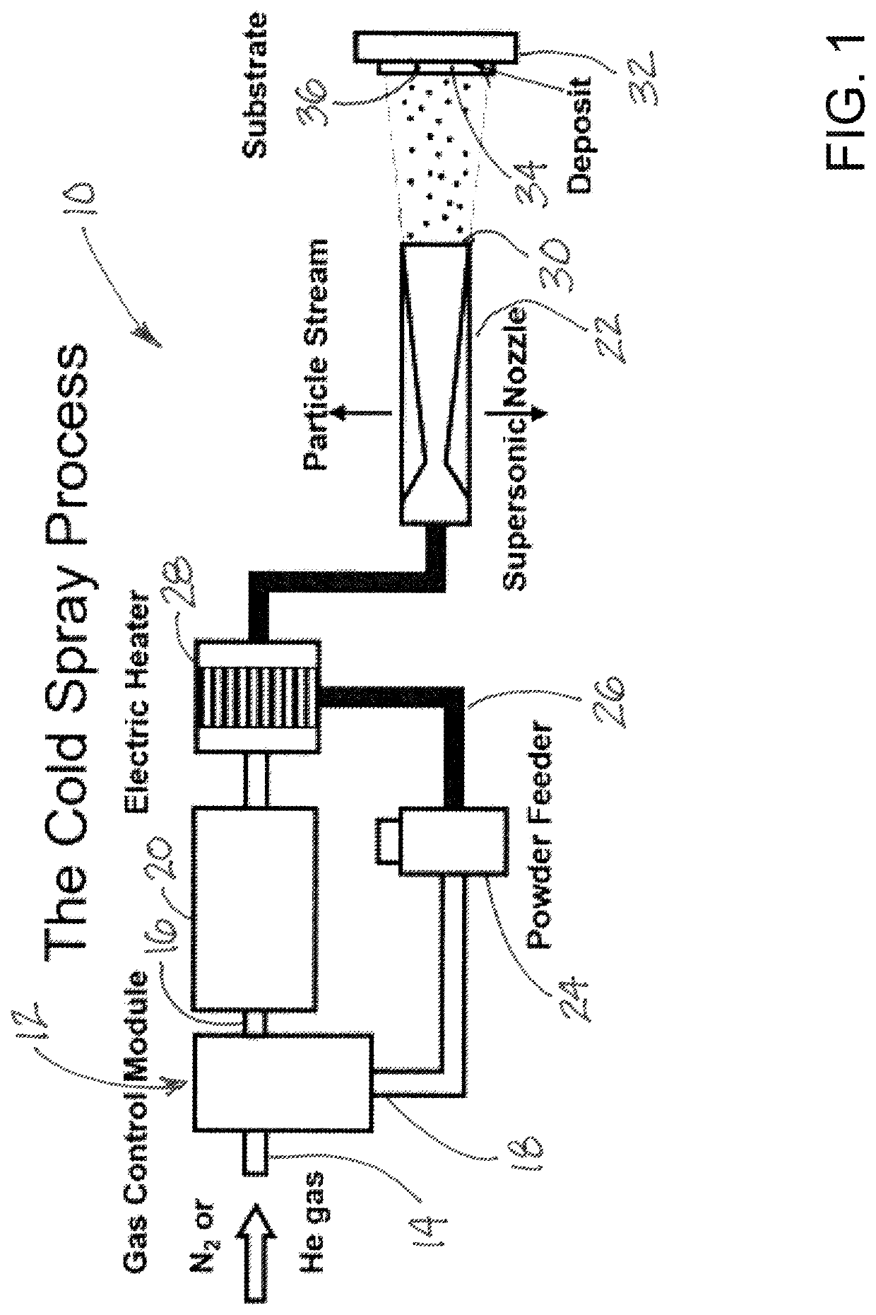
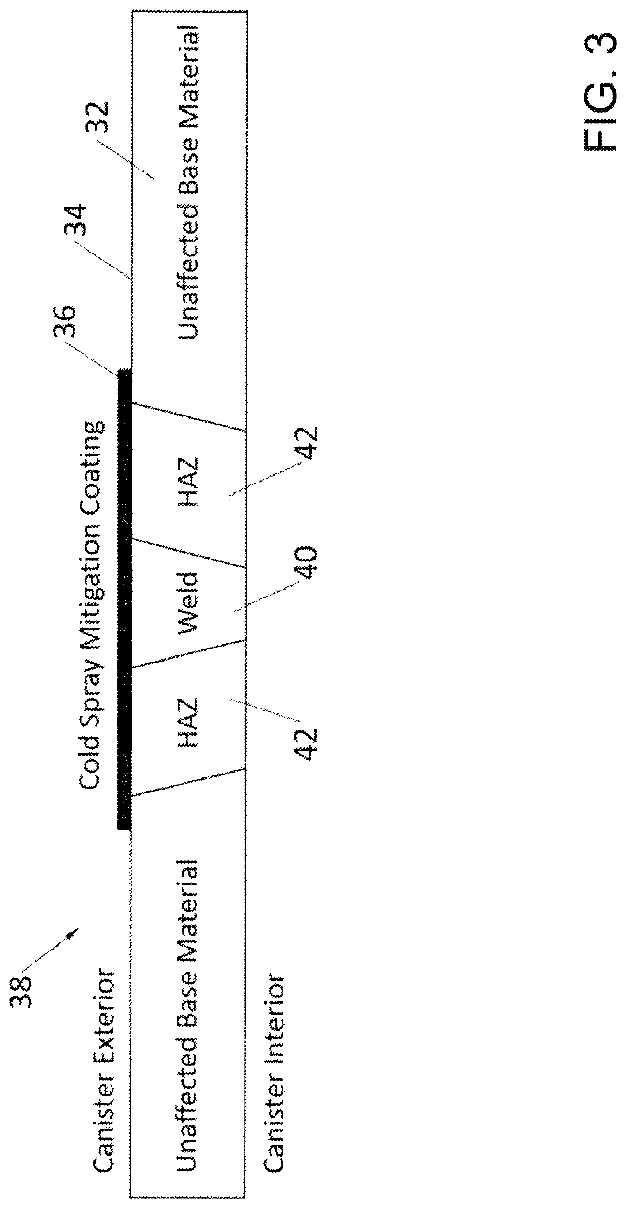
[0057]Using the cold spray process, it is possible to deposit many different types of metals and alloys. Aspects of the present disclosure were developed through iterative process improvement of several cold spray materials. The table of FIG. 7D lists several of the materials investigated in this process, including 304L stainless steel, 316L stainless steel, 904L stainless steel, Inconel 625, and Alloy 59. To determine the efficacy of cold spray materials for CISCC prevention, the materials listed in the table of FIG. 7D were cold sprayed on small-scale V-notch welded specimens, comprised of 304L material, ¼″ thick, welded with a single pass wire feed process using 308 weld wire. Cold spray coatings of 304L, 316L, 904L, Inconel 625, and Alloy 59 were deposited over the weld and HAZ on a single side of the welded coupon to a thickness of 0.010 to 0.025 inches using previously developed processing conditions with a VRC Metal Systems Gen III high pressure cold spray system. Samples wer...

example 2

[0063]In a highly advantageous implementation of the present disclosure, the cold spray repair and / or mitigation coating is robotically applied in-situ, which is defined as being applied without moving, manipulating, exposing, or otherwise disturbing the loaded HWC system. In this implementation, the robotic system is used to navigate the vent opening located on the hazardous or nuclear waste storage HWC, e.g. DCSS. Navigation through the vent opening places significant limitations on the size of the apparatus moving through the vent opening, and requires specific miniaturized geometry for embodiments of the disclosure. Illustratively, the robotic crawler must be able to traverse multiple 90° corner features prior to reaching the gap formed between the steel-lined overpack and the HWC to access the stainless-steel HWC itself. The cold spray robot crawler may then navigate in the gap using integrated navigation cameras to the damage site while pulling the flexible cold spray hose.

[00...


PUM

PropertyMeasurementUnit
Thicknessaaaaaaaaaa
Pressureaaaaaaaaaa
Flow rateaaaaaaaaaa

Abstract

Systems and methods for application of stress corrosion cracking resistant cold spray coatings include a method of forming a partial coating on a canister having a perimeter wall with a surface. The method may include identifying a compromised region on the surface of the wall of the canister, and impacting a substantially linear flow of particles of a powder against an area in the compromised region of the surface in a manner effective to cause the particles of the powder to bond to the surface of the wall to produce a coating on the area of the compromised region. The method may also include moving the substantially linear flow in a direction substantially parallel to the surface of the wall to cause the particles to impact an additional area of the compromised region to cause the particles to bond to the surface of the additional area.

Description

REFERENCE TO RELATED APPLICATIONS[0001]This application claims the benefit of U.S. Provisional Patent Application No. 62 / 715,398, filed Aug. 7, 2018 and U.S. Provisional Patent Application No. 62 / 865,486, filed Jun. 24, 2019, each of which is hereby incorporated by reference herein in its entirety.STATEMENT REGARDING FEDERALLY SPONSORED RESEARCH OR DEVELOPMENT[0002]This invention was made with government support under DE-SC0017855 awarded by Department of Energy. The government has certain rights in the inventionBACKGROUNDField[0003]The present disclosure relates to coating systems and more particularly pertains to new systems and methods for application of stress corrosion cracking resistant cold spray coatings for mitigation and repair of compromised regions of a container.Description of the Prior Art[0004]There is a critical need for a minimally invasive mitigation and repair technology to mitigate environmental, corrosion, shipping, and accidental damage to hazardous waste stora...

Claims


Application Information

Patent Timeline
IPC IPC(8): B23P6/00C23C24/04B05B7/14G21F5/00
CPCB23P6/00B05B7/144C23C24/04G21F5/00C23C24/08C23C24/082C23C24/085C23C24/087B05B13/0431B05B13/005B05B13/0426B05B7/1613B05B13/0618
Inventor JOHNSON, KYLE WILLIAMBEARD, JAMIE WALTERJASTHI, BHAARAT KUMAR
Owner JOHNSON KYLE WILLIAM
Why Eureka
Try Eureka