Composite agitator

a technology of agitator and composite material, which is applied in the field of agitator, can solve the problems of large glass vessel, difficult to manufacture, and essentially impossible after a certain size, and achieve the effects of good temperature resistance, excellent chemical resistance, and light weigh

Active Publication Date: 2022-04-26
GMM PFAUDLER US INC
View PDF13 Cites 8 Cited by
  • Summary
  • Abstract
  • Description
  • Claims
  • Application Information

AI Technical Summary

Benefits of technology

[0016]The agitator thus is lighter weight than prior art agitators that are entirely glass coated steel or other metal, yet still has excellent chemical resistance and good temperature resistance. Further the agitator of the invention reduces likelihood of glass spalling and mechanical damage, including impact damage, cavitation damage and damage from static discharge. Further, the construction of the agitators of the invention permits agitator blade shapes not practical in glass coated agitators in the prior art.

Problems solved by technology

While steel has superior strength and fabrication properties, it nevertheless is subject to corrosion.
The corrosion problem, to some extent, was addressed with glass vessels and components but large glass vessels were difficult to manufacture and after a certain size was essentially impossible.
In addition, glass, while exceptionally strong, is subject to fracture if the surface is even slightly marred.
As such, entirely glass vessels and components, of sizes having a large capacity, e.g. in excess of 200 liters, could not be reliably used under significant pressure and were problematic for safety reasons.
Therefore, for example, sulfuric acid, that was first made in small glass containers, was later made in lead, which forms very toxic compounds
Unfortunately, most of such enamels themselves had one or more other negative properties, e.g. insufficient adhesion, poor temperature resistance, toxicity and poor corrosion resistance.
The manufacture of glass lined steel containers was, however, very problematic due to the problem of adhesion and differences in coefficient of expansion between steel and glass.
The glass coatings were therefore subject to crazing, spalling and failure.
While these agitators have been extremely useful in the art, there are still major problems that limit their use.
The weight of a glass lined steel agitator is high causing difficulties in assembly and handling.
Further, due to the high mass of glass coated mixing agitators, high rates of rotation cannot be easily be used due to large energy input required, and the development of huge centrifugal forces.
Further, rates of rotation cannot be quickly changed due to high kinetic energy of rotation.
In addition, due to requirements for rounded profiles, agitator shape is limited.
High shear glass coated agitators with sharp edges are not possible and curved or otherwise shaped glass coated agitator blades are more subject to coating failure.
Also, high mass agitators are difficult to balance with precision.
Unfortunately, plastics simply do not have sufficient mechanical strength to replace the steel that is required for large vessels subject to high temperatures and pressures.
Additionally, unlike glass, very few plastics are able to withstand attack by almost all chemicals and to withstand elevates temperatures, e.g. as high as 250 degrees Celcius (about 500 degrees Fahrenheit).
Certain fluoropolymers do have such chemical and heat resistance, e.g. polytetrafluoroethylene (PTFE) but unfortunately have notoriously low yield strength and low tensile strength.
In addition, due to low thermal conductivity and high melt viscosity, PTFE is not heat extrudable and is thus is very difficult to work with, e.g. requiring expensive machining and large waste to form desired shapes and / or a complex ten step sintering or fusion process.

Method used


Image

  • Composite agitator
  • Composite agitator
  • Composite agitator

Examples


Embodiment Construction

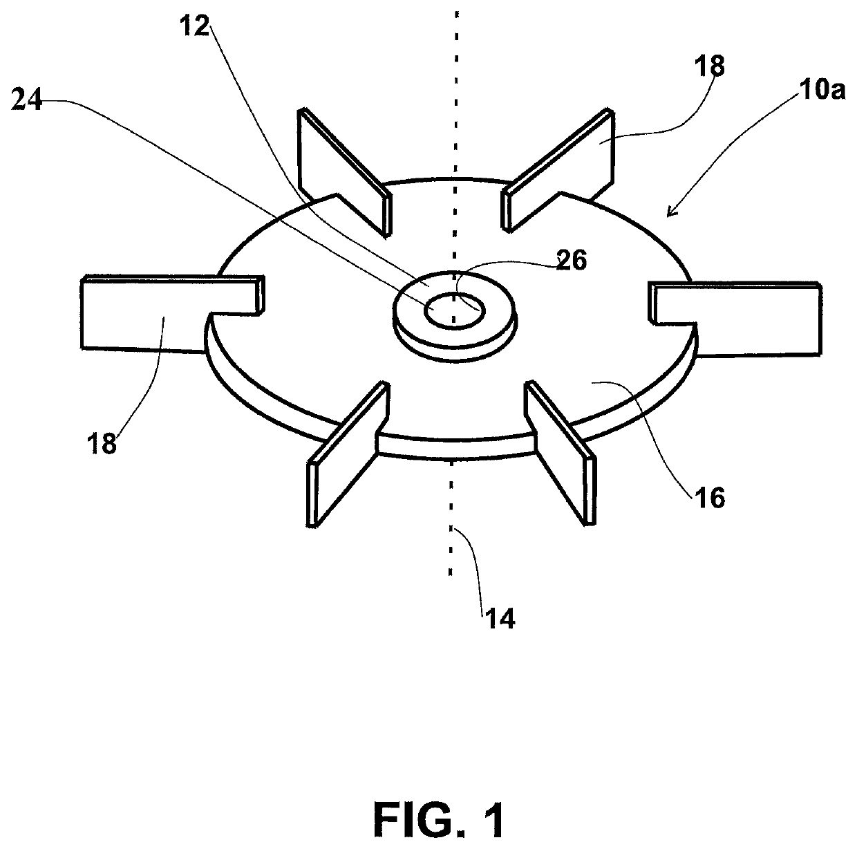
[0022]As used herein, “agitator” is intended to mean the rotating portion of a mixer having blades, or the equivalent, that cause mixing turbulence. Such agitators have also been historically referred to in the art as turbines or impellers.

[0023]The invention is a mixing agitator that overcomes or reduces disadvantages associated with glass coated mixing agitators in the prior art as discussed in the Background of the invention.

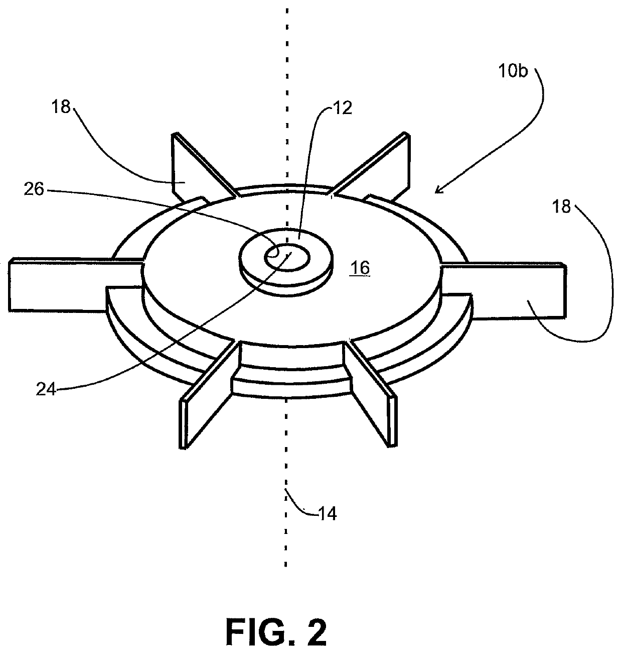
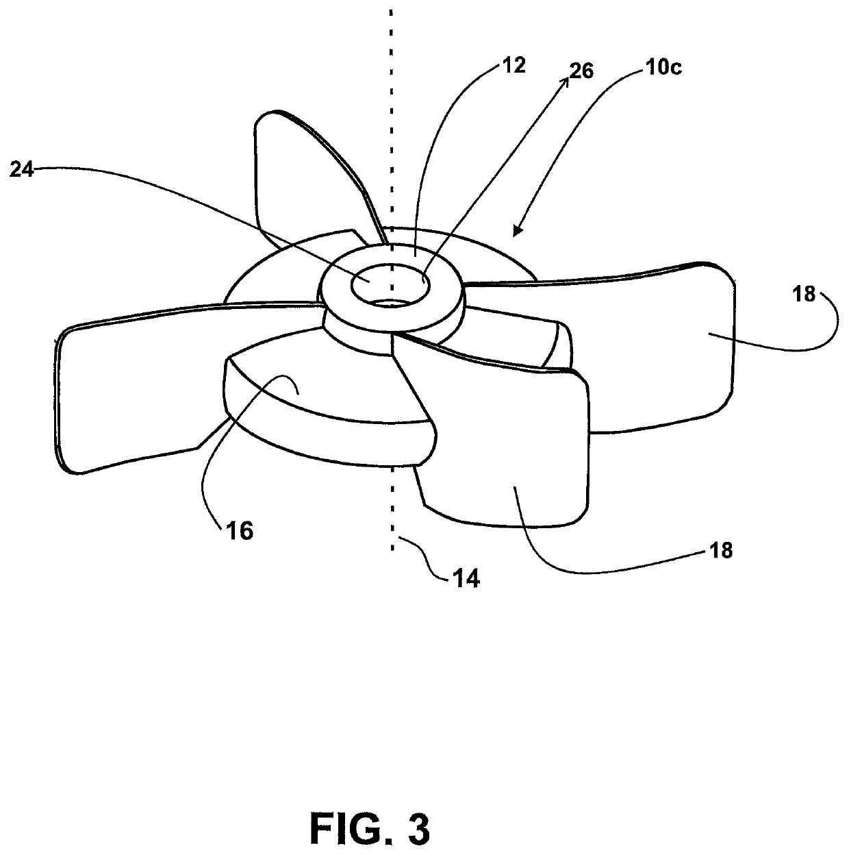
[0024]In particular, the blades of the agitator of the invention, being made of fluorinated polymer, eliminates the problem concerning damage at corners and edges of glass coated blades. In accordance with the invention, blades can thus be made with shapes, sharp edges and corners, while retaining other advantages of glass coated glass coated agitators including chemical resistance and good heat resistance.

[0025]In addition, the agitator weight is dramatically reduced thus requiring less energy input to cause the agitator to reach a desired high speed and to ...


PUM

PropertyMeasurementUnit
temperaturesaaaaaaaaaa
strengthaaaaaaaaaa
temperatureaaaaaaaaaa

Abstract

A mixing agitator, for industrial use in mixing processes, that overcomes disadvantages associated with glass coated mixing agitators in the prior art. In particular, the mixing agitator includes a glass coated metal hub radially symmetrical about a central axis. The hub is at least partially embedded within a fluorinated polymer. The fluorinated polymer extends beyond the hub and forms agitator blades that may be reinforced. The hub has a centrally located receiving portion for receiving a drive shaft for rotating the agitator. The agitator is lighter weight than prior art glass coated steel agitators yet still has excellent chemical resistance and good temperature resistance. The agitator of the invention reduces likelihood of glass damage and permits agitator blade shapes not useable by glass coated agitators in the prior art. The invention also includes a mixing apparatus incorporating the hub and a method for mixing using the agitator.

Description

TECHNICAL FIELD[0001]This invention relates to agitators used in agitation (mixing) of substances.BACKGROUND ART[0002]It is well understood that mixing processes of one kind or another have been used for centuries, e. g. processing of foods, making solutions for medical and other reasons, for making of pottery and building materials, for coatings and adhesives, and for chemical processing and reactions.[0003]As the world became industrialized, mixing needs became ever more important and required advances for ever more thorough blending and required ever more resistance of equipment to corrosion, higher temperature, higher pressures, better containment, low toxic content and sanitation.[0004]Many such industrialized mixers took place in steel containers and had steel agitators. While steel has superior strength and fabrication properties, it nevertheless is subject to corrosion. The corrosion problem, to some extent, was addressed with glass vessels and components but large glass ves...

Claims


Application Information

Patent Timeline
Patent Type & Authority Patents(United States)
IPC IPC(8): B22C5/00B01F27/053B01F27/07B01F27/1111
CPCB01F27/0531B01F27/071B01F27/1111B01F27/053
Inventor GOLDSMITH, MARKGRUVER, III, MORRIS (BUD)KEYES, MIKERAU, STEVEN E.
Owner GMM PFAUDLER US INC
Why Eureka
Try Eureka