
Power module assembly

a power module and assembly technology, applied in the field of power electronics, can solve the problems of increasing the turn-off loss of the device, reducing the reliability of the device, and so as to facilitate the power module assembly and reduce the parasitic inductance and the emi. , the effect of reducing the parasitic inductance and the emi

Active Publication Date: 2022-09-13
DELTA ELECTRONICS SHANGHAI CO LTD
View PDF40 Cites 0 Cited by
  • Summary
  • Abstract
  • Description
  • Claims
  • Application Information

AI Technical Summary

Benefits of technology

The present invention provides a power module assembly that optimizes the arrangement of components to reduce parasitic inductance and EMI. The two switches are connected in series to form a bridge arm embedded in a package body. This structure reduces the size of the power module and improves power density. The first and second high-frequency loops are decoupled from each other, which simplifies the connection process and reduces assembly costs. The system bus set provides better shielding for the control circuit and facilitates heat dissipation. The aims of reducing costs, improving reliability, and reducing thermal resistance are achieved.

Problems solved by technology

Therefore, a higher voltage spike is caused by larger stray inductance when the current change rate keeps constant.
The voltage spike will reduce the reliability of the device and increase turn-off-loss of the device.
At the same time, due to the unavoidable presence of parasitic inductance in the power loop, the high switching frequency of the power device causes a rapid voltage change, which will cause the EMI in the circuit to exceed the standard.

Method used


Image

  • Power module assembly
  • Power module assembly
  • Power module assembly

Examples


first embodiment

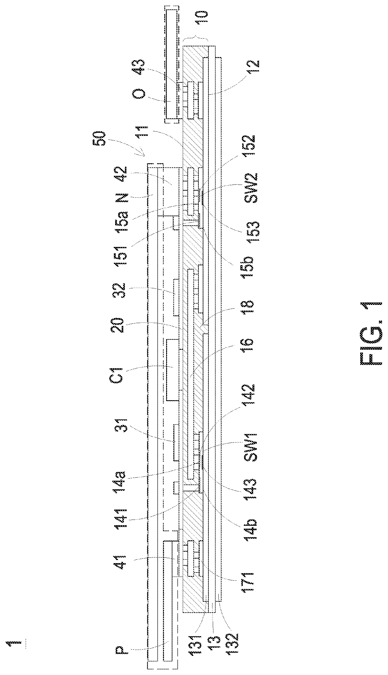
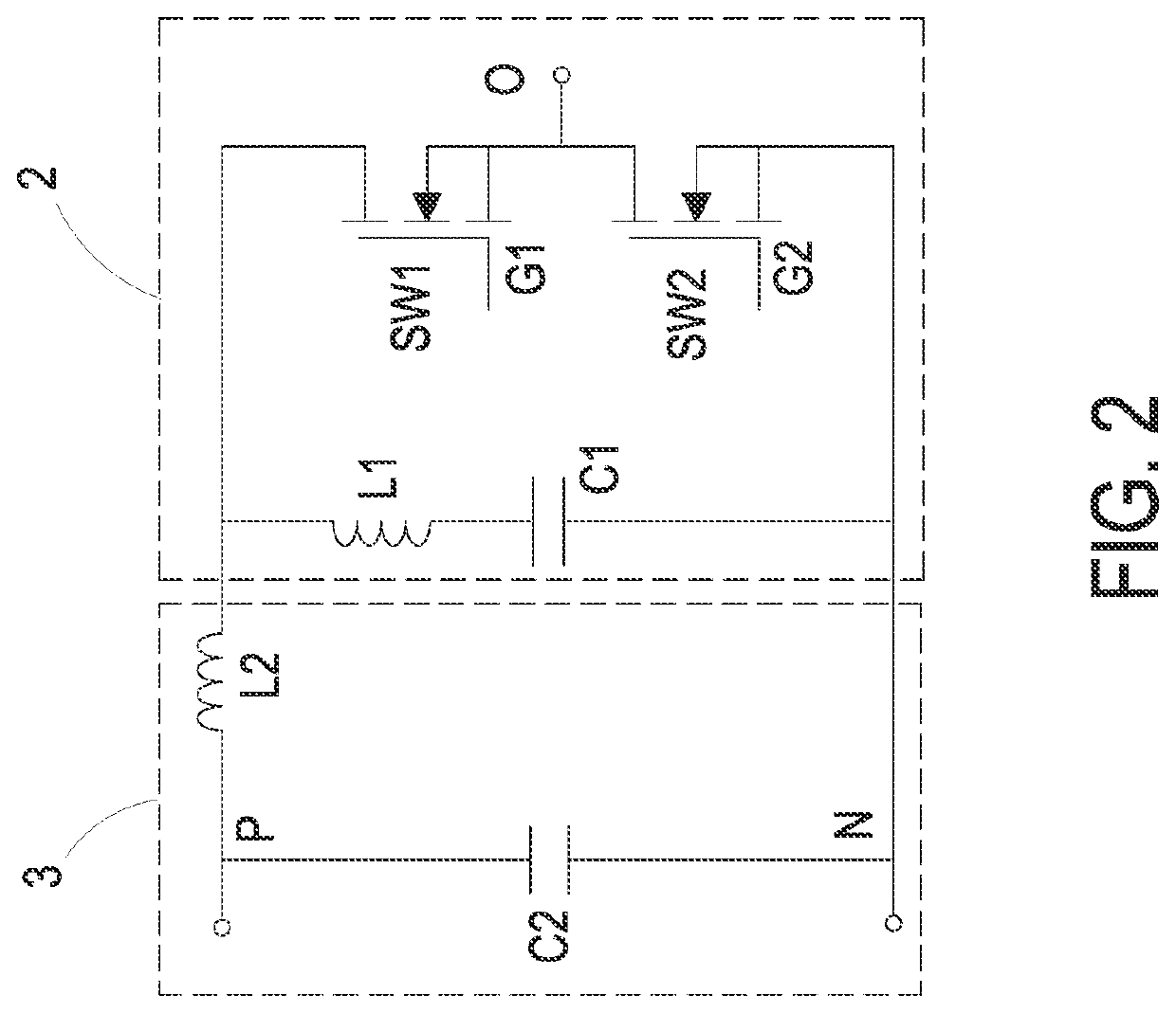
[0058]FIG. 1 is a schematic cross-sectional view illustrating a power module assembly according the present disclosure. FIG. 2 is an equivalent circuit diagram showing the power module assembly of the present disclosure. In the embodiment, the power module assembly 1 is for example but not limited to an assembly structure of an embedded power module and a system end connected thereto. The power module assembly 1 includes package body 10, a first wiring layer 20, a capacitor C1 and a system bus set 50. The package body 10 includes a first surface 11, a second surface 12, a first switch SW1 and a second switch SW2. The first surface 11 and the second surface 12 are opposite to each other. In the embodiment, the first switch SW1 and the second switch SW2 are embedded between the first surface 11 and the second surface 12, and connected to each other in series to form a bridge arm. The first wiring layer 20 is disposed on the first surface 11 of the package body 10. The capacitor C1 is ...

second embodiment

[0075]FIG. 8 is a perspective view illustrating a partial structure of the power module assembly according to the present disclosure. In the embodiment, the signal terminals of the two driving components 31 and 32 are connected to the control-electrode lead-out ports for the first switch SW1 and the second switch SW2 through the connector The connector is a mature connection method in the power electronics industry, and has the advantages of convenience, simplicity and reliability. On the other hand, in the embodiment, the capacitor C1 and the driving components 31 and 32 are disposed on the first wiring layer 20 outside the package body 10 by the surface mount technology (SMT). Since the capacitor C1 and other low-priced, large-quantity, stress-sensitive devices are arranged outside the package body 10, the assembly structure is simplified, and it has the advantages of reducing the cost, simplifying the manufacturing process, and improving the yield and the reliability of the produ...

sixth embodiment

[0087]FIG. 14 is a schematic cross-sectional view illustrating the power module assembly according to the present disclosure. In the embodiment, the structures, elements and functions of the power module assembly 1e are similar to those of the power module 1 of FIG. 1 and FIGS. 6A and 6B, and are not redundantly described herein. In the embodiment, the second wiring layer 131 of the substrate 13 further includes a metal bump 133, which is disposed on the second wiring layer 131 of the substrate 13 and is configured to provide a conductive function. Preferably but not exclusively, in the embodiment, the bump 133 is formed by half-etching process after the copper layer is coated on the insulation substrate. It has advantages of omitting the conductive structure 171 (referring to FIG. 1), reducing the number of components, facilitating the control of incoming materials and reducing the welding requirements. Consequently, it makes the process simpler and more reliable, and the feasibili...


PUM


Abstract

A power module assembly is disclosed and includes a package body, a first wiring layer, a capacitor, and a system bus set. The package body includes a first surface, a second surface and two switches connected in series to form a bridge arm between the first surface and the second surface. The first wiring layer is disposed on the first surface. The capacitor is connected in parallel with the bridge arm to form a first high-frequency loop. The system bus set includes a positive-electrode bus and a negative-electrode bus fanned out from the first surface, respectively. The projection of the positive-electrode bus or / and the negative-electrode bus on the first surface is at least partially overlapped with the projection of the two switches on the first surface. The bridge arm is electrically connected between the positive-electrode bus and the negative-electrode bus to form a second high-frequency loop.

Description

CROSS-REFERENCE TO RELATED APPLICATION[0001]This application claims priority to China Patent Application No. 202010806375.2, filed on Aug. 12, 2020. This application is a continuation-in-part application of U.S. application Ser. No. 16 / 502,175 filed on Jul. 3, 2019, and entitled “POWER MODULE STRUCTURE”. The entire contents of the above-mentioned patent applications are incorporated herein by reference for all purposes.FIELD OF THE INVENTION[0002]The present disclosure relates to the field of power electronics, and more particularly to a power module assembly.BACKGROUND OF THE INVENTION[0003]As an important part of power conversion, modern power electronic equipment is widely used in the power, electronics, motor and energy industries. To ensure long-term stable operation of power electronic equipment and improve power conversion efficiency of power electronic equipment has been an important goal of those skilled in the art.[0004]As the core component of modern power electronic equi...

Claims


Application Information

Patent Timeline
Patent Type & Authority Patents(United States)
IPC IPC(8): H05K1/14H01L23/538H01L23/552H01L23/66H01L23/522H01L23/367H01L23/528H01L25/18
CPCH01L23/552H01L23/367H01L23/5223H01L23/5283H01L23/5286H01L23/66H01L25/18H01L23/49H01L23/49838H01L23/5385H01L25/072H01L2224/291H01L2224/2929H01L2224/293H01L2224/32245H01L2224/8384H01L25/16H01L23/3735H01L23/50H01L23/36H01L2224/32227H01L2224/18H05K7/14329H01L2924/014H01L2924/00014
Inventor HONG, SHOUYUTONG, YANZHOU, WEICHENGLIAN, DONGFANGCAO, HAIYANGXU, HAIBINWANG, TAOXIE, YICONG
Owner DELTA ELECTRONICS SHANGHAI CO LTD
Learn More