Anatomical fixation implant

anatomical fixation and implant technology, applied in the field of anatomical fixation implants, can solve the problems of irritating the rim of the joint cavity, affecting the effect of the implant, and presently known bioabsorbable fixation implants for attaching soft tissue to bone, etc., and achieve the effect of advantageous surgical us

Inactive Publication Date: 2001-06-21
BIONX IMPLANTS
View PDF0 Cites 34 Cited by
  • Summary
  • Abstract
  • Description
  • Claims
  • Application Information

AI Technical Summary

Benefits of technology

0029] However, a general feature of orientation, fiber-reinforcement or self-reinforcement of the implants of this invention is that many of the reinforcing elements are oriented in such a way that they can carry effectively the different external loads (such as tensile, bending and shear loads) that are directed to the healing tissue (for example, loads to the shoulder joint caused by the movements of the muscles in the arm and/or in the upper part of patient's body).
0030] According to

Problems solved by technology

However, the presently known bioabsorbable fixation implants for attaching soft tissue to bone have encountered several problems in clinical use, especially in rotator cuff or labrum rupture fixation.
Additionally, that part of the symmetric head (on the right side of the shaft in FIG. 1) which does not bind the soft tissue, is unnecessary for healing and can irritate the rim of the joint cavity.
However, this implant is expressly restricted to those applications where no forces will be exerted on the implant that will tend to pull it out of the bone.
This implant does not effectively grip the drill hole in the bone to resist tensile forces, because the leg portion is constructed s

Method used


Image

  • Anatomical fixation implant
  • Anatomical fixation implant
  • Anatomical fixation implant

Examples


Embodiment Construction

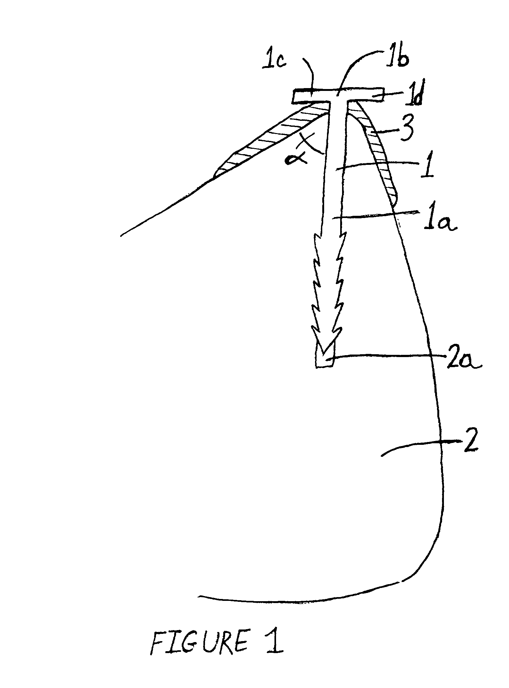
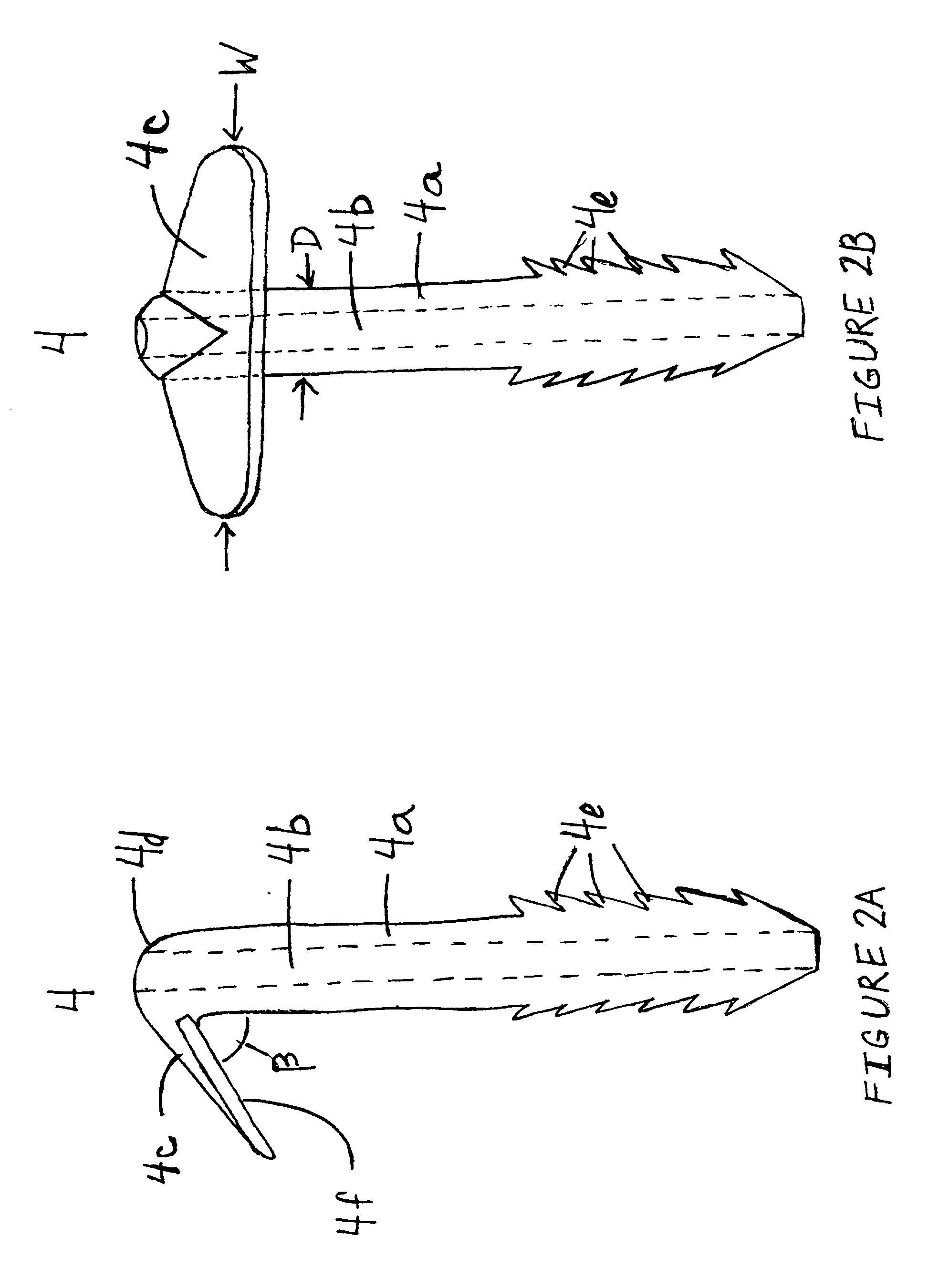
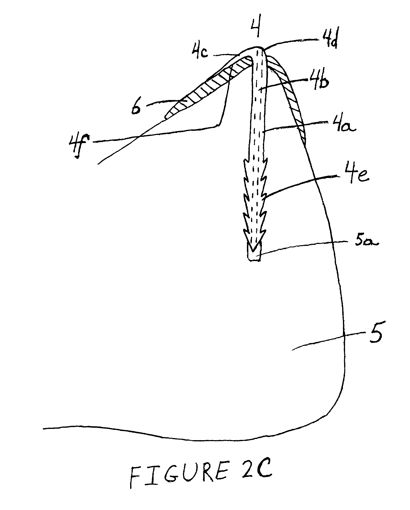
[0035] A single screw extruder was applied to manufacture a poly-L / DL-lactide (L / DL molar ratio 70 / 30, inh. viscosity 5.8 dl / g, trade name Resomer LR 708, manufacturer Boehringer Ingelheim, Germany) 8.6 mm thick cylindrical continuous billet, which was cooled to room temperature. The cooled billet was heated to 70.degree.C. and it was drawn to the draw ratio of 3 according to PCT / FI 96 / 00511, Example 1, the entire disclosure of which is incorporated herein by way of this reference, to increase the strength and ductility of the material. The final oriented part had the diameter of 5 mm. The oriented part was cut into rods of 40 mm length. A hole of diameter 1.1 mm was drilled through the rods along the long axis of the rods. A 10 mm long segment at the end of the rods was located between two heated steel plates (T=80.degree.C.) which were compressed to flatten the end of the rod to the thickness of 1 mm. At the same time the non-compressed part (shaft) of the rod was bent in relation...


PUM


Abstract

This invention relates in general to a bioabsorbable surgical tissue fixation implant (nail) and, more particularly to an implant for the fixation of soft tissue to bone. In one embodiment of the invention, the fixation implant generally includes at least one shaft configured to securely fit into a hole formed in bone. The shaft is of sufficient length relative to the interior diameter of the hole and, in some preferred embodiments, has locking protuberances, like threads, ridges, or barbs, that resist removal of the shaft from the hole in the bone when different types of forces, such as tensile or bending forces, are applied to the implant. The shaft is generally cylindrical in shape, however, in various embodiments of the invention, different cross-sections could be used. In a preferred embodiment of the present invention, the implant has a flattened and bent end portion emerging from only one side of the shaft. At the other side of the implant the outer surface of the shaft and the emerging end portion form a smooth surface, without any projections. This smooth surface at the end of the implant prevents irritation of the surrounding tissue. The end portion has a mating surface configured to grip a portion of the soft tissue surrounding the hole between the bone and the mating surface. The longitudinal axis of the shaft is oriented at an angle of less than 90 degrees relative to the mating surface. In this fashion, the implant anchors soft tissue, such as rotator cuff tissue, to bone.

Description

[0001] This invention relates in general to a bioabsorbable surgical tissue fixation implant (nail) and, more particularly to an implant for the fixation of soft tissue to bone.[0002] In such procedures as rotator cuff surgery or labrum rupture fixation surgery and hand tendon surgery, tendons or other soft tissues are fixed to bone. The tendons or other tissue are often secured to bone by feeding the soft tissue through holes formed in the bone and suturing the tissue in place. Another method of securing soft tissue to bone employs a fixation device which essentially tacks the tendon to bone. Unless the tendon or other soft tissue is completely immobilized, the fixation device must be securely embedded in the bone to hold the tendon or other soft tissue stationary against the bone surface, resisting those forces tending to pull the tendon or soft tissue away from the bone surface, until the tendon or soft tissue has become attached to the bone. Another method of securing tendon and...

Claims


Application Information

Patent Timeline
IPC IPC(8): A61B17/04A61F2/02A61B17/56A61F2/08
CPCA61F2/0811A61F2002/0858A61F2002/0888
Inventor BURKHEAD, W.TORMALA, PERTTIHAPPONEN, HARRIHELEVIRTA, PERTTIKAIKKONEN, AUVOPOHJONEN, TIMO
Owner BIONX IMPLANTS
Why Eureka
Try Eureka