Feedback circuit and amplifier and mixer comprising the same

a feedback circuit and amplifier technology, applied in the field of feedback circuits, can solve problems such as intermodulation distortion, variable disturbance waves, and the inability to perform setting such that a particular frequency is not fed back

Inactive Publication Date: 2001-07-19
SANYO ELECTRIC CO LTD
View PDF0 Cites 18 Cited by
  • Summary
  • Abstract
  • Description
  • Claims
  • Application Information

AI Technical Summary

Problems solved by technology

It has been known that the harmonics cause various disturbance waves as intermodulation distortions.
That is, it is impossible to perform setting such that a particular frequency is not fed back.
As a result, the characteristics of the amplifier and particularly, the gain thereof is degraded.
A matching circuit for impedance matching with a load circuit connected to the amplifier is difficult to design.
Accordingly, the circuit scale is significantly increased, and the power consumption in the circuits is also increased.
Consequently, the power amplifier designed for a certain communication system cannot be applied to another communication system which differs in the channel bandwidth.

Method used


Image

  • Feedback circuit and amplifier and mixer comprising the same
  • Feedback circuit and amplifier and mixer comprising the same
  • Feedback circuit and amplifier and mixer comprising the same

Examples


first embodiment

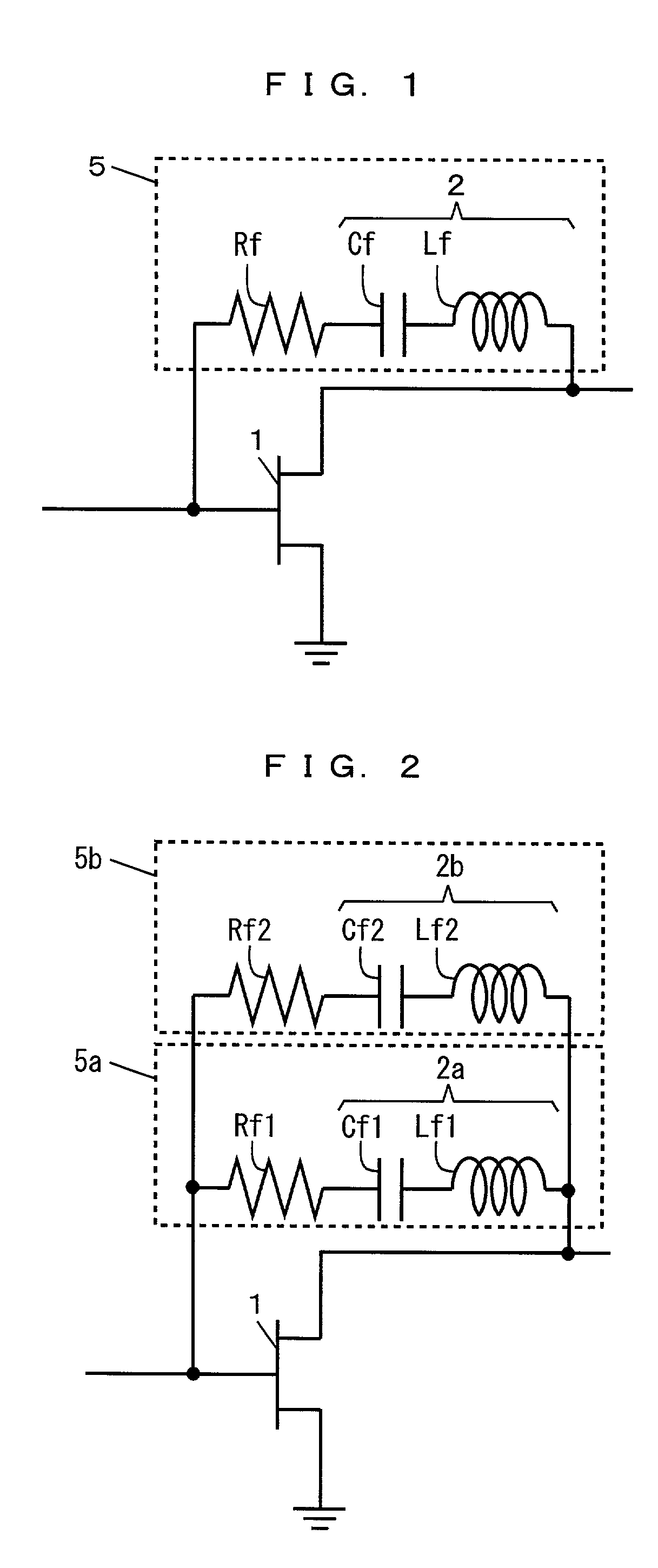
[0091] FIG. 1 is a circuit diagram of an amplifier comprising a feedback circuit in the present invention.

[0092] In FIG. 1, a feedback circuit 5 is connected between a drain electrode (an output terminal) and a gate electrode (an input terminal) of an FET 1. The feedback circuit 5 is constituted by a series connection of a feedback amount adjusting resistor Rf and an LC series resonance circuit 2. The LC series resonance circuit 2 is constituted by a series connection of a capacitor Cf and an inductor Lf.

[0093] As a first example, the capacitance value of the capacitor Cf and the inductance of the inductor Lf are set such that the LC series resonance circuit 2 enters a short-circuited state, that is, the impedance of the LC series resonance circuit 2 becomes zero with respect to an m-th harmonic by resonating at the frequency of the m-th harmonic, and the LC series resonance circuit 2 enters an opened state, that is, the impedance of the LC series resonance circuit 2 increases to in...

second embodiment

[0096] FIG. 2 is a circuit diagram of an amplifier comprising a feedback circuit in the present invention.

[0097] In FIG. 2, two feedback circuits 5a and 5b are connected in parallel between a drain electrode and a gate electrode of an FET 1. The feedback circuit 5a is constituted by a series connection of an LC series resonance circuit 2a and a feedback amount adjusting resistor Rf1. The LC series resonance circuit 2a is constituted by a series connection of a capacitor Cf1 and an inductor Lf1. Similarly, the feedback circuit 5b is constituted by a series connection of an LC series resonance circuit 2b and a feedback amount adjusting resistor Rf2. The LC series resonance circuit 2b is constituted by a series connection of a capacitor Cf2 and an inductor Lf2.

[0098] For example, the capacitance value of the capacitor Cf1 and the inductance of the inductor Lf1 are set such that the LC series resonance circuit 2a enters a short-circuited state with respect to an m-th harmonic by resonat...

third embodiment

[0139] FIG. 12 is a circuit diagram of a mixer comprising a feedback circuit in the present invention.

[0140] In FIG. 12, a feedback circuit 5 is connected between a drain electrode and one gate electrode of an FET 1a. The configuration of the feedback circuit 5 is the same as the configuration of the feedback circuit 5 shown in FIG. 1. In the mixer, a high frequency signal RF is inputted to one gate electrode of the FET 1a, and a local oscillation signal LO is inputted to the other gate electrode thereof. Further, an intermediate frequency signal IF is outputted from the drain electrode of the FET 1a.

[0141] In the mixer according to the present embodiment, the feedback circuit 5 is provided, as in the amplifiers in the first and second embodiments, thereby making it possible to reduce distortion represented by adjacent channel leakage power or the like with respect to the same input power. The output power of a fundamental wave is increased by reducing the distortion, thereby making...


PUM


Abstract

A feedback circuit is connected between a drain electrode and a gate electrode of an FET. The feedback circuit is constituted by a series connection of a feedback amount adjusting resistor and an LC series resonance circuit. The LC series resonance circuit is constituted by a series connection of a capacitor and an inductor. The capacitance of the capacitor and the inductance of the inductor are set such that the LC series resonance circuit enters a short-circuited state with respect to an m-th harmonic by resonating at the frequency of the m-th harmonic, and the LC series resonance circuit enters an opened state with respect to a fundamental wave.

Description

[0001] 1. Field of the Invention[0002] The present invention relates to a feedback circuit provided in a transistor and an amplifier and a mixer comprising the same.[0003] 2. Description of the Background Art[0004] In recent years, radio waves having a great many frequencies have been required in order to establish communication with the rapid development of mobile communication. The frequencies of the radio waves used in the mobile communication have been shifted to a microwave band. A handy terminal for such mobile communication is provided with an amplifier using a field effect transistor (hereinafter referred to as FET). There is a method of providing a feedback circuit in one of the designs of the amplifier.[0005] FIG. 26 is a circuit diagram of an amplifier comprising a conventional feedback circuit.[0006] As shown in FIG. 26, a feedback circuit 200 comprising a resistor 101 and a capacitor 102 is connected between a drain electrode (an output terminal) and a gate electrode (a...

Claims


Application Information

Patent Timeline
Patent Type & Authority Applications(United States)
IPC IPC(8): H03D7/12H03H7/01H03F1/34H03F1/38H03H11/12
CPCH03H11/1213H03F1/34H03D7/12H03H7/01
Inventor NISHIDA, MASAOSAWAI, TETSURO
Owner SANYO ELECTRIC CO LTD
Why Eureka
Try Eureka