Wireless location using signal fingerprinting

a signal fingerprinting and wireless technology, applied in direction finders using radio waves, instruments, wireless communication, etc., can solve the problems of high cost, significant distortion, and special-purpose electronics that are required to achieve the effect of low cost, low cost and spectrum efficiency

Inactive Publication Date: 2001-09-20
TRACBEAM
View PDF45 Cites 735 Cited by
  • Summary
  • Abstract
  • Description
  • Claims
  • Application Information

AI Technical Summary

Benefits of technology

0200] The MBS 148 acts as a low cost, partially-functional, moving base station, and is, in one embodiment, situated in a vehicle where an operator may engage in MS 140 searching and tracking activities. In providing these activities using CDMA, the MBS 148 provides a forward link pilot channel for a target MS 140, and subsequently receives unique BS pilot strength measurements from the MS 140. The MBS 148 also includes a mobile station for data communication with the LC 142, via a BS 122. In particular, such data communication includes telemetering the geographic position of the MBS 148 as well as various RF measurements related to signals received from the target MS 140. In some embodiments, the MBS 148 may also utilize multiple-beam fixed antenna array elements and / or a moveable narrow beam antenna, such as a microwave dish 182. The antennas for such embodiments may have a known orientation in orderto further deduce a radio location of the target MS 140 with respect to an estimated current location of the MBS 148. As will be described in more detail herein below, the MBS 148 may further contain a global positioning system (GPS), distance sensors, dead-reckoning electronics, as well as an on-board computing system and display devices for locating both the MBS 148 of itself as well as tracking and locating the target MS 140. The computing and display provides a means for communicating the position of the target MS 140 on a map display to an operator of the MBS 148.
0201] Each location base station (LBS) 152 is a low cost location device. Each such LBS 152 communicates with one or more of the infrastructure base stations 122 using one or more wireless technology interface standards. In some embodiments, to provide such LBS's cost effectively, each LBS 152 only partially or minimally supports the air-interface standards of the one or more wireless technologies used in communicating with both the BSs 122 and the MSs 140. Each LBS 152, when put in service, is placed at a fixed location, such as at a traffic signal, lamp post, etc., and wherein the location of the LBS may be determined as accurately as, for example, the accuracy of the locations of the infrastructure BSs 122. Assuming the wireless technology CDMA is used, each BS 122 uses a time offset of the pilot PN sequence to identify a forward CDMA pilot channel. In one embodiment, each LBS 152 emits a unique, time-offset pilot PN sequence channel in accordance with the CDMA standard in the RF spectrum designated for BSs 122, such that the channel does not interfere with neighboring BSs 122 cell site channels, nor would it interfere with neighboring LBSs 152. However, as one skilled in the art will understand, time offsets, in CDMA chip sizes, may be re-used within a PCS system, thus providing efficient use of pilot time offset chips, thereby achieving spectrum efficiency. Each LBS 152 may also contain multiple wireless receivers in order to monitor transmissions from a target MS 140. Additionally, each LBS 152 contains mobile station 140 electronics, thereby allowing the LBS to both be controlled by the LC 142, and to transmit information to the LC 142, via at least one neighboring BS 122.

Problems solved by technology

However, these systems have drawbacks that include high expense in that special purpose electronics are required.
Furthermore, the systems are generally only effective in line-of-sight conditions, such as rural settings.
Radio wave surface reflections, refractions and ground clutter cause significant distortion, in determining the location of a signal source in most geographical areas that are more than sparsely populated.
Moreover, these drawbacks are particularly exacerbated in dense urban canyon (city) areas, where errors and / or conflicts in location measurements can result in substantial inaccuracies.
However, the GPS is impractical in many applications.
Accordingly, inclement weather conditions, such as clouds, terrain features, such as hills and trees, and buildings restrict the ability of the GPS receiver to determine its position.
Furthermore, the initial GPS signal detection process for a GPS receiver is relatively long (i.e., several minutes) for determining the receiver's position.
Such delays are unacceptable in many applications such as, for example, emergency response and vehicle tracking.
These systems have been found to be awkward and have met with limited success.
Such systems have also met with limited success.
In brief, each of the various GPS embodiments have the same fundamental problems of limited reception of the satellite signals and added expense and complexity of the electronics required for an inexpensive location mobile station or handset for detecting and receiving the GPS signals from the satellites.
The behavior of a mobile radio signal in the general environment is unique and complicated.
Efforts to perform correlations between radio signals and distance between a base station and a mobile station are similarly complex.
Coverage problems can take up to a year to resolve.
Sheffer acknowledges that terrain variations affect accuracy, although as noted above, Sheffer's disclosure does not account for a sufficient number of variables, such as fixed and variable location shadow fading, which are typical in dense urban areas with moving traffic.
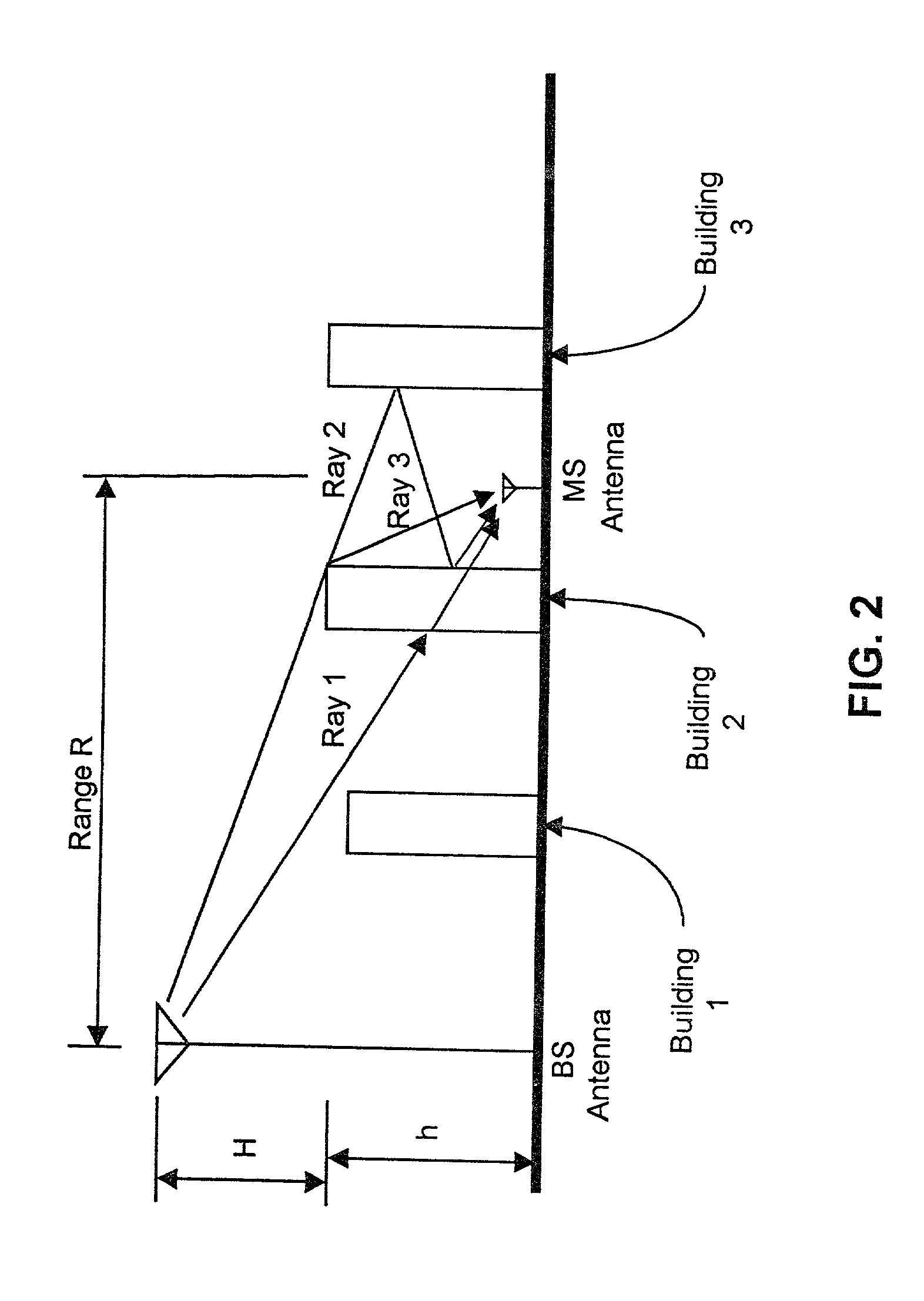
However, a substantial difficulty with the two-ray model in practice is that it requires a substantial amount of data regarding building dimensions, geometries, street widths, antenna gain characteristics for every possible ray path, etc.
Additionally, it requires an inordinate amount of computational resources and such a model is not easily updated or maintained.
Unfortunately, in practice clutter geometries and building heights are random.
Moreover, data of sufficient detail has been extremely difficult to acquire, and regression standard fit errors are poor; i.e., in the general case, these errors were found to be 40-60 dB.
Thus the two-ray model approach, although sometimes providing an improvement over single ray techniques, still did not predict RF signal characteristics in the general case to level of accuracy desired (<10 dB).
Although some data held very correlations, other data and environments produced poor results.
Accordingly, his results appear unreliable for use in general location context.
However, these results alone have not been sufficiently robust and general to accurately locate an MS, due to the variable nature of urban clutter spatial arrangements.
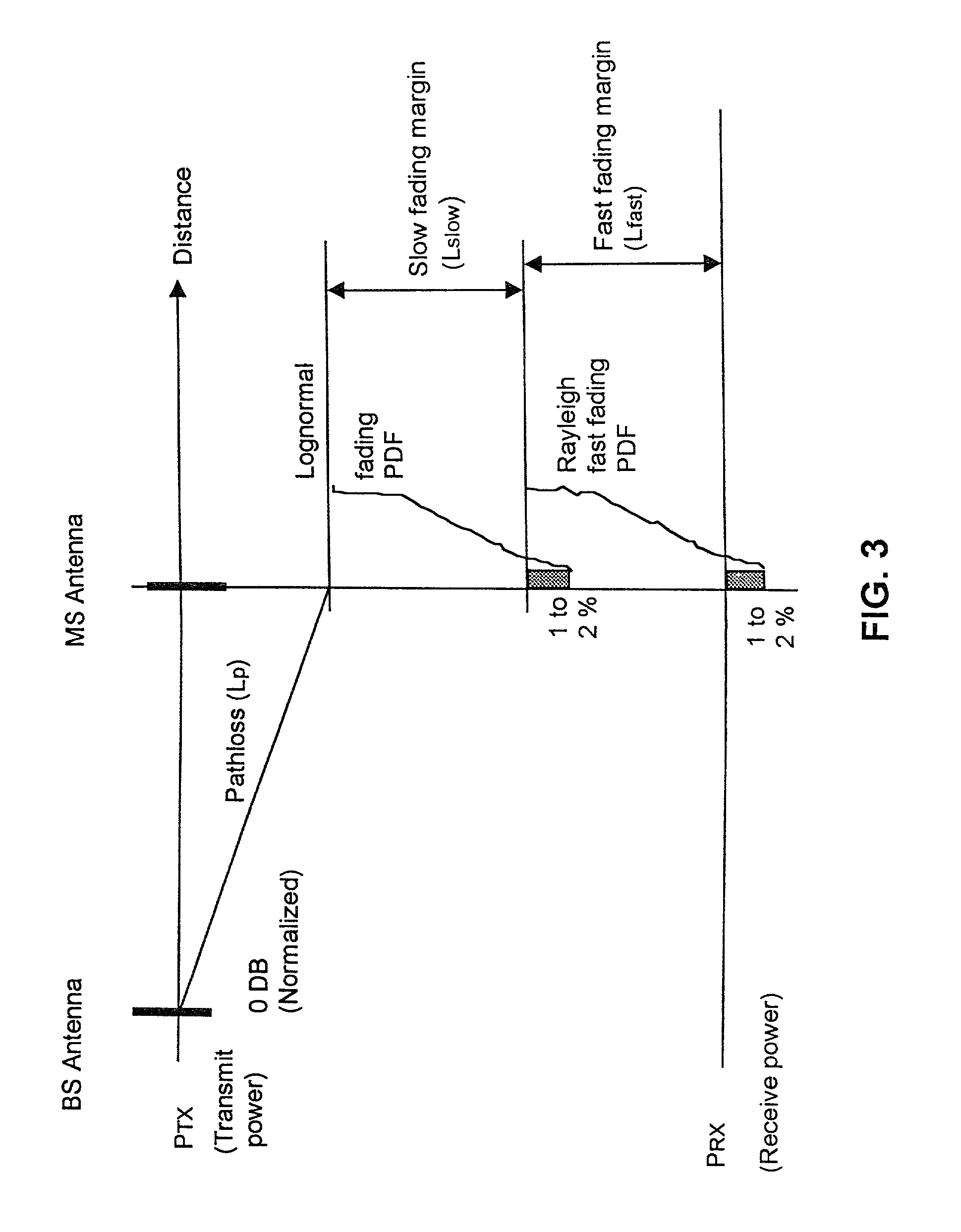
However, in the worst-case scenario both fading margins are simultaneously exceeded, thus causing a fading margin overload.

Method used


Image

  • Wireless location using signal fingerprinting
  • Wireless location using signal fingerprinting
  • Wireless location using signal fingerprinting

Examples


Embodiment Construction

: Historical Data Confidence Adjuster Program Historical_data_confidence_adjuster(loc_hyp) / * This function adjusts the confidence of location hypothesis, "loc_hyp", according to how well its location signature cluster fits with verified location signature clusters in the location signature data base. * / { mesh <-- get_mesh_for(loc_hyp.FOM_ID); / / each FOM has a mesh of the Location Center service area covering <--get_mesh_covering_of_MS_estimate_for(loc_hyp); / * get the cells of "mesh" that minimally cover the most pertinent target MS estimate in "loc_hyp". * / total_per_unit_error <-- 0; / / initialization for each cell, C, of "covering" do / * determine an error measurement between the location signature cluster of "loc_hyp" and the verified location signature clusters in the cell * / { centroid <-- get_centroid(C); error_obj <--DB_Loc_Sig_Error_Fit(centroid,C,loc_hyp.loc_sig_cluster, "USE ALL LOC SIGS IN DB"); / * The above function call computes an error object, "error_obj", providing ...


PUM


Abstract

A location system is disclosed for commercial wireless telecommunication infrastructures. The system is an end-to-end solution having one or more location centers for outputting requested locations of commercially available handsets or mobile stations (MS) based on, e.g., CDMA, AMPS, NAMPS or TDMA communication standards, for processing both local MS location requests and more global MS location requests via, e.g., Internet communication between a distributed network of location centers. The system uses a plurality of MS locating technologies including those based on: (1) two-way TOA and TDOA; (2) pattern recognition; (3) distributed antenna provisioning; and (4) supplemental information from various types of very low cost non-infrastructure base stations for communicating via a typical commercial wireless base station infrastructure or a public telephone switching network. Accordingly, the traditional MS location difficulties, such as multipath, poor location accuracy and poor coverage are alleviated via such technologies in combination with strategies for: (a) automatically adapting and calibrating system performance according to environmental and geographical changes; (b) automatically capturing location signal data for continual enhancement of a self-maintaining historical data base retaining predictive location signal data; (c) evaluating MS locations according to both heuristics and constraints related to, e.g., terrain, MS velocity and MS path extrapolation from tracking and (d) adjusting likely MS locations adaptively and statistically so that the system becomes progressively more comprehensive and accurate. Further, the system can be modularly configured for use in location signaling environments ranging from urban, dense urban, suburban, rural, mountain to low traffic or isolated roadways. Accordingly, the system is useful for 911 emergency calls, tracking, routing, people and animal location including applications for confinement to and exclusion from certain areas.

Description

[0001] The present invention is directed generally to a system and method for locating people or objects, and in particular, to a system and method for locating a wireless mobile station using a plurality of simultaneously activated mobile station location estimators.[0002] Introduction[0003] Wireless communications systems are becoming increasingly important worldwide. Wireless cellular telecommunications systems are rapidly replacing conventional wire-based telecommunications systems in many applications. Cellular radio telephone networks ("CRT"), and specialized mobile radio and mobile data radio networks are examples. The general principles of wireless cellular telephony have been described variously, for example in U.S. Pat. No. 5,295,180 to Vendetti, et al, which is incorporated herein by reference.[0004] There is great interest in using existing infrastructures for wireless communication systems for locating people and / or objects in a cost effective manner. Such a capability ...

Claims


Application Information

Patent Timeline
Patent Type & Authority Applications(United States)
IPC IPC(8): G01S1/02G01S5/00G01S19/09G01S5/02G01S5/06G01S19/46H04W64/00
CPCG01S1/026G01S1/028G01S5/0009G01S5/0018G01S5/0054G01S5/02G01S5/0205G01S5/021G01S5/0252G01S5/0257G01S5/0278G01S5/06G01S2205/006G01S2205/008H04W64/00H04W4/025G01S5/0244
Inventor KARR, CHARLES L. JR.DUPRAY, DENNIS J.
Owner TRACBEAM
Why Eureka
Try Eureka