Working oil filter device for continuously variable transmission
a technology of working oil filter and transmission, which is applied in the direction of gear lubrication/cooling, gearing elements, gearing, etc., can solve the problems of cavitation in the pump, cvt function lowering, and valves stuck
- Summary
- Abstract
- Description
- Claims
- Application Information
AI Technical Summary
Benefits of technology
Problems solved by technology
Method used
Image
Examples
first embodiment
[0033] the invention will be described in detail with reference to the accompanying drawings.
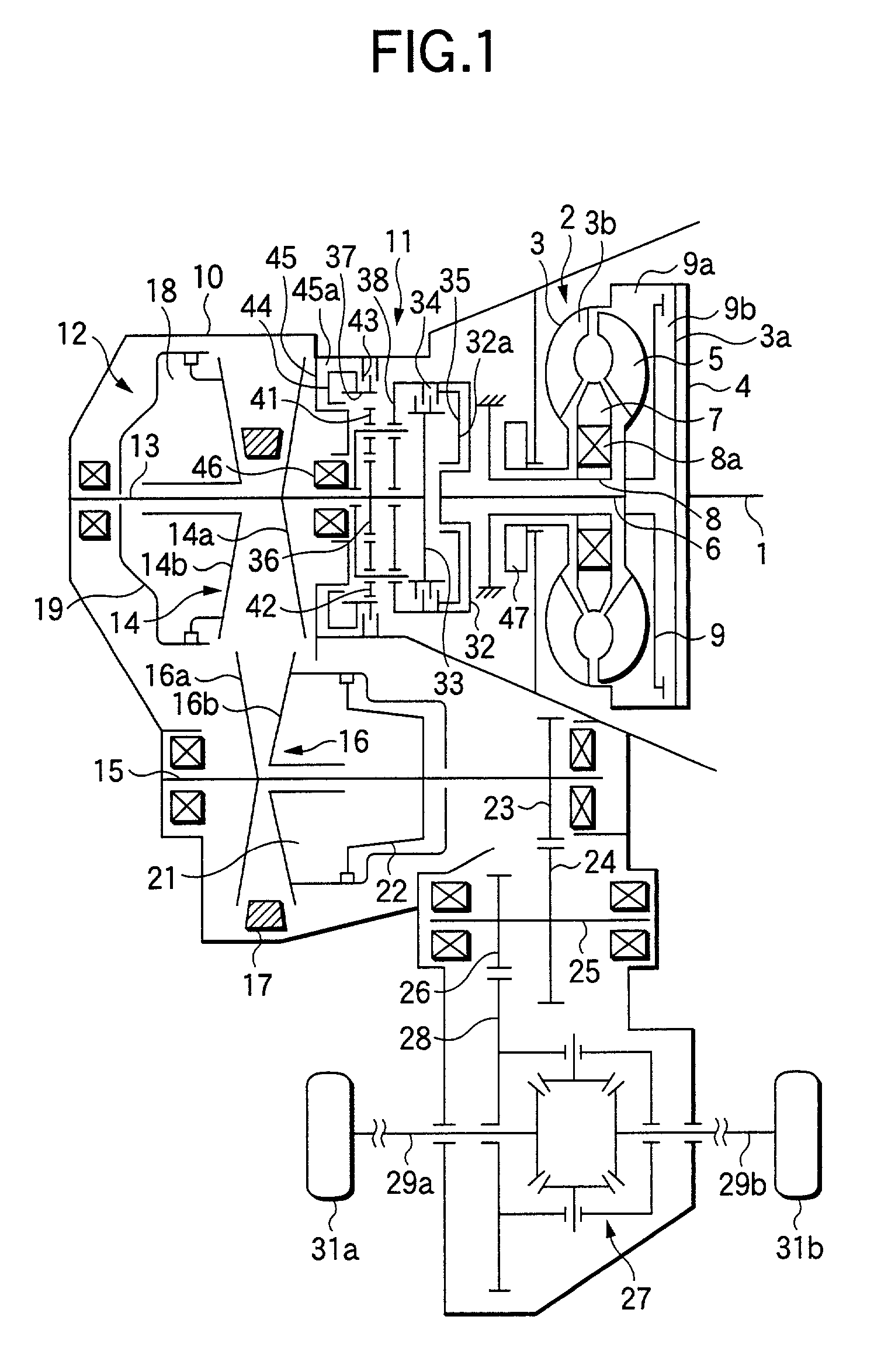
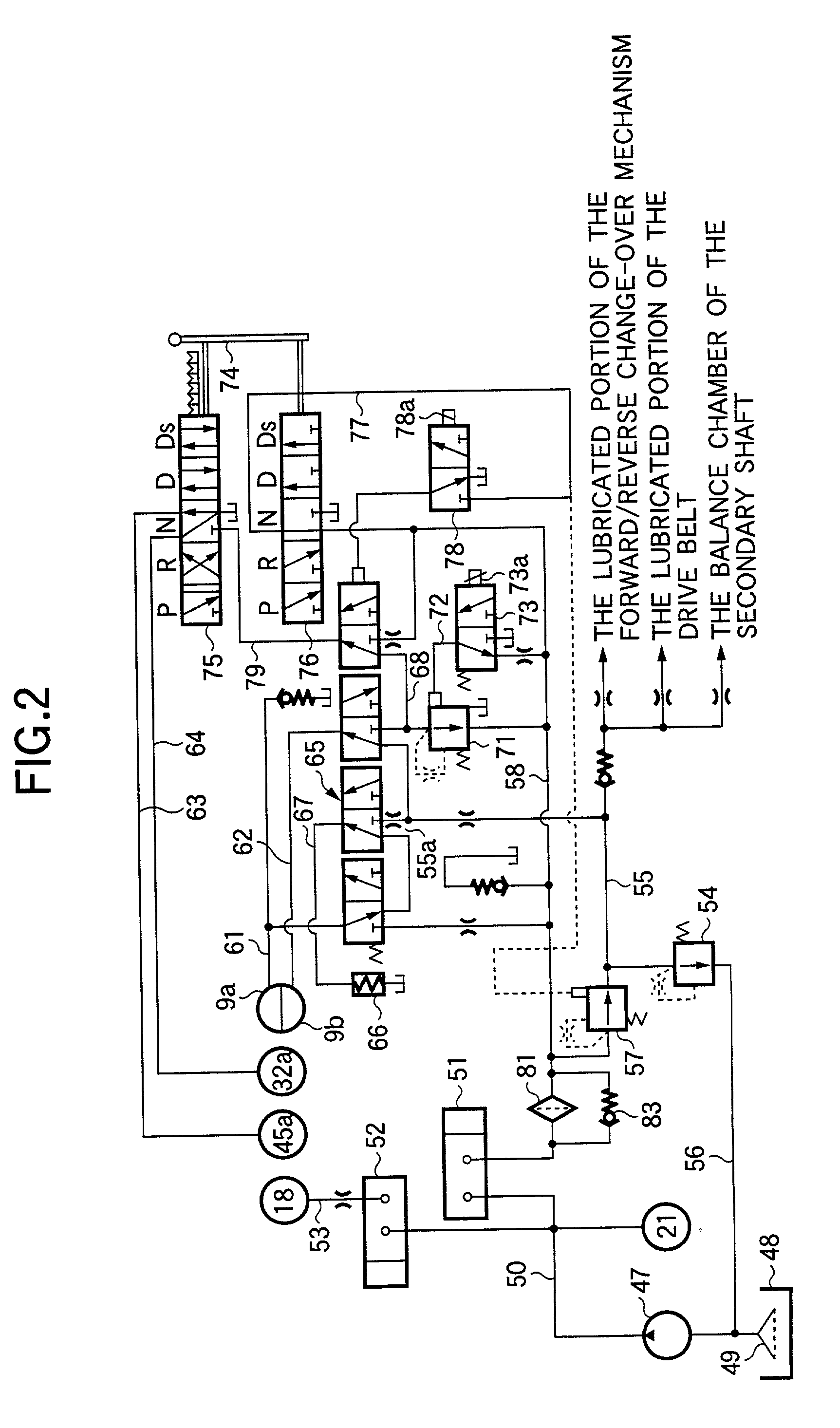
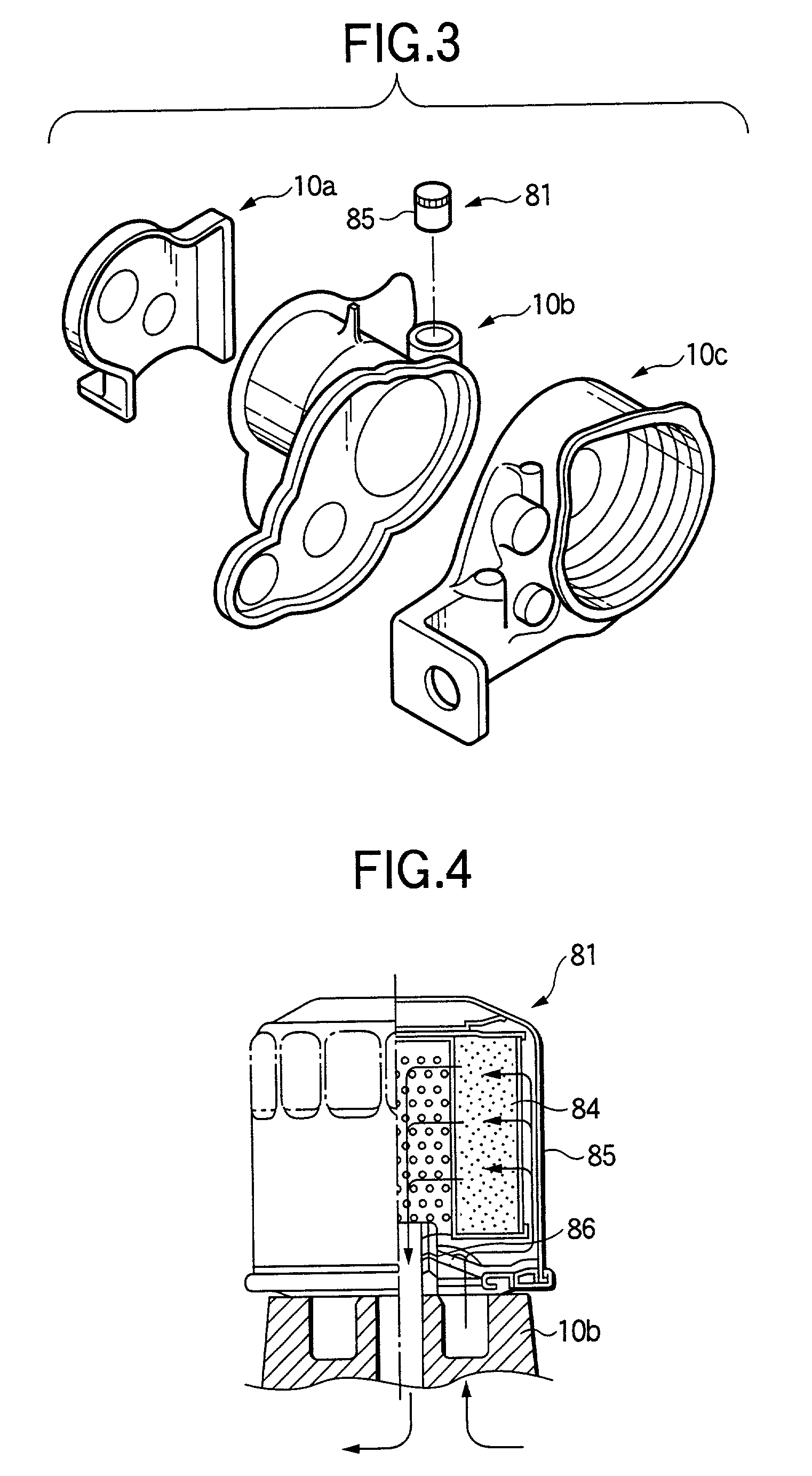
[0034] FIG. 1 is a schematic diagram showing one example of a drive system of a belt type continuously variable transmission, i.e., a CVT. A crankshaft 1, as driven by the not-shown engine, is directly connected to a front cover 3a of a pump side casing 3 of a torque converter 2 through a drive plate 4, and a turbine runner 5, as arranged to confront a pump impeller 3b disposed in the pump side casing 3, is directly connected to a turbine shaft 6. Between the pump impeller 3b and the turbine runner 5, there is arranged a stator 7 which is supported by a one-way clutch 8a mounted on a stator supporting shaft 8. To the turbine shaft 6, there is directly connected a lockup clutch 9 which can move to an engagement position, in which it engages with the front cover 3a, and a release position in which it is disengaged. The power of the engine is transmitted through the torque converter 2 or the lo...
second embodiment
[0073] Next, the invention will be described in detail with reference to the accompanying drawings.
[0074] The second embodiment of the invention is basically identical to the first embodiment of the invention in construction. Thus, only different features will be described below. In the following description of the second embodiment, like reference numerals are imparted to like members or members having like functions to those described in the first embodiment of the invention previously, and therefore, the detailed description thereof will be omitted.
[0075] FIG. 5 is a circuit diagram showing the hydraulic circuit of the CVT of this embodiment.
[0076] The discharge port of the oil pump 47 is connected via a secondary pressure passage or a line pressure passage 50 with not only the secondary oil chamber 21 for actuating the movable pulley 16b of the secondary pulley 16 but also a secondary pressure port of a secondary pressure adjust valve 251. By this secondary pressure adjust valve...
third embodiment
[0095] Further, the invention will be described in detail with reference to the accompanying drawings.
[0096] The third embodiment of the invention is basically identical to the first embodiment of the invention in construction. Thus, only different features will be described below. In the following description of the second embodiment, like reference numerals are imparted to like members or members having like functions to those described in the first embodiment of the invention previously, and therefore, the detailed description thereof will be omitted.
[0097] FIG. 8 is a circuit diagram showing the hydraulic circuit of the CVT of this embodiment. The line pressure passage 350 is connected to the input port of a clutch pressure adjust valve 357, and a clutch pressure passage 358 is connected to the output port of the same. Via this clutch pressure passage 358, the working oil is fed to the clutch oil chamber 32a of the forward clutch 34 and the brake oil chamber 45a of the reverse b...
PUM
 Abstract
Description
Claims
Application Information
 - R&D
- Intellectual Property
- Life Sciences
- Materials
- Tech Scout
- Unparalleled Data Quality
- Higher Quality Content
- 60% Fewer Hallucinations
Browse by: Latest US Patents, China's latest patents, Technical Efficacy Thesaurus, Application Domain, Technology Topic, Popular Technical Reports.
© 2025 PatSnap. All rights reserved.Legal|Privacy policy|Modern Slavery Act Transparency Statement|Sitemap|About US| Contact US: help@patsnap.com


