Method for manufacturing a floor covering

a manufacturing method and technology for floor coverings, applied in the direction of cork mechanical work, mechanical apparatus, non-woven fabrics, etc., to achieve the effects of easy control, controlled scattering, and high processing speed

Inactive Publication Date: 2001-10-11
HINDS TERENCE MARTIN +2
View PDF0 Cites 16 Cited by
  • Summary
  • Abstract
  • Description
  • Claims
  • Application Information

AI Technical Summary

Benefits of technology

[0014] In a particularly preferred embodiment of the invention, the substrate is a fibre matt material, especially a glass fibre matt material. Preferably, the fibre matt has less than 100 g, ideally less than 65 g and most preferably from 30 to 50 g of glass fibre per m.sup.2 of material. This material is easily handled in roll form and provides the required reinforcing strength.
[0016] Ideally, for ease of use the nipping means comprises a pair of nip rollers defining a gap therebetween. Preferably the method includes the step of adjusting the gap between the nip rollers. In this way the process is readily tailored to a desired final product.
[0076] The material that is scattered on the substrate may be in any suitable form such as powder, granules or pellets. A blended powder may be extruded to produce a fully fused compound which is then pelletised and in some cases pulverised. Such pellets have the advantage that they are more easy to control and are less adherent to the belts generally than powders. Thus, a more controlled scattering, higher processing speed and a more uniform product may be achieved. Typically the pellets are from 0.5 to 2 mm diameter, preferably about 1 mm, and from 1 to 2 mm long, preferably about 1.5 mm. The pulverised particles are generally in the 100 to 500 micron range.

Problems solved by technology

There are a number of problems with such manufacturing techniques.

Method used


Image

  • Method for manufacturing a floor covering
  • Method for manufacturing a floor covering
  • Method for manufacturing a floor covering

Examples


example 2

[0086] A foamed basecoat material may be applied to a saturated substrate using the following basecoat dry blend formulation:

2 Parts by Weight Suspension Grade PVC 95-100 Dispersion Grade PVC 0-5 Di-2-Ethyl Hexyl Phthalate 20-50 Butyl Benzyl Phthalate 20-50 Calcium Carbonate Filler 20-80 Barium / Zinc Stabiliser 1.5-3.5 Blowing Agent Mixture 2-4 (Azodicarbonamide / Zinc Oxide) Titanium dioxide 6-10

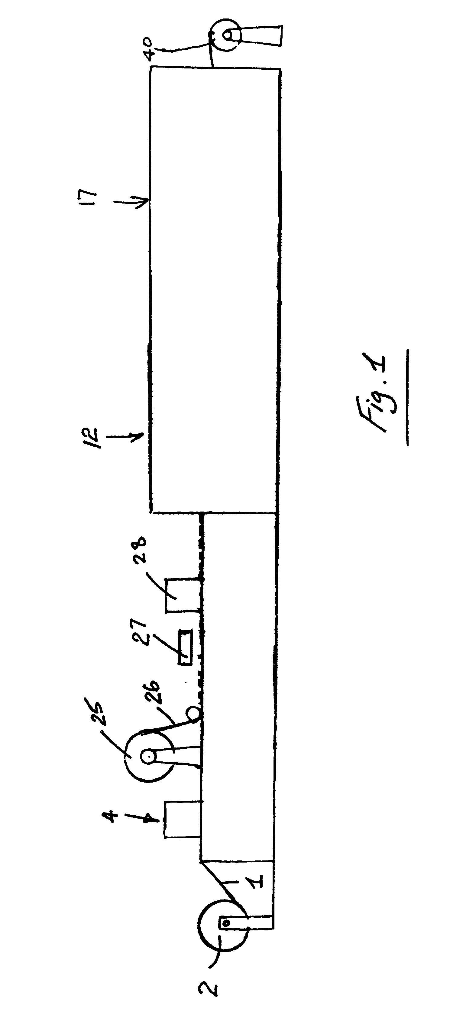
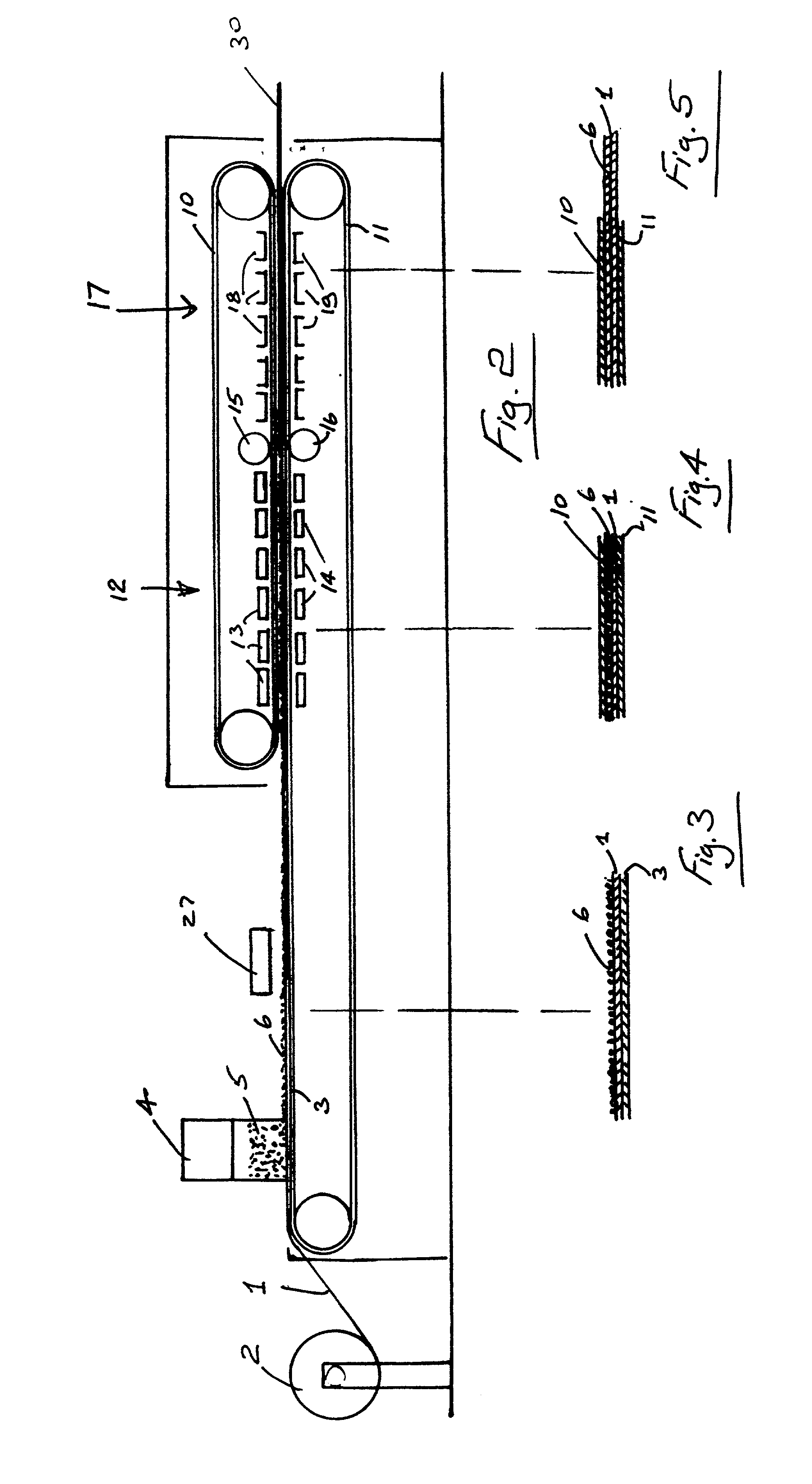
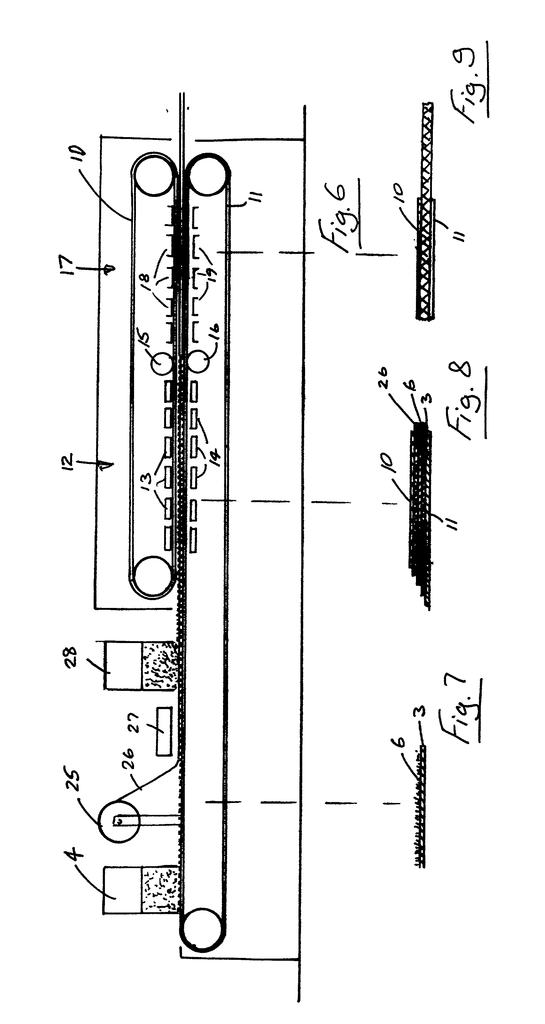
[0087] The foamable basecoat material is scattered onto the saturated substrate at a single scattering station at a rate of from 250-450 g / m.sup.2 and further processed as described above in Example 1.

[0088] It will be appreciated that the method is applicable to producing non directional homogeneous floor covering materials.

[0089] It will also be appreciated that while the invention has been described particularly in relation to PVC material it may also be applied to any suitable thermoplastics materials which are substantially free of PVC.

[0090] Many variations on the specific embodiments of...


PUM

PropertyMeasurementUnit
temperatureaaaaaaaaaa
thermoplasticaaaaaaaaaa
heataaaaaaaaaa

Abstract

A method for manufacturing a floor covering involves leading a glass fiber matt 1 from a supply reel 2 onto a conveyor belt 3. At a first scattering station 4, a saturation material is scattered onto the matt 1 to form a scattered layer. The matt 1 is then led between upper and lower heated belts 10, 11 to gel the scattered layer. The belts are then passed between a pair of smoothing / nipping rollers to form a layer of uniform thickness. The belts are then cooled and the matt 1 with saturation layer applied is wound for further processing. In an alternative arrangement a saturation material is scattered directly onto a substrate belt at the first scattering station 4, a glass fiber matt 26, is applied over the scattered material and, at a second scattering station 28, an amount of the saturation material or a different material is scattered onto the matt 26.

Description

[0001] The invention relates to a method for manufacturing a floor covering and in particular to a method for manufacturing a polymeric, for example, a vinyl floor covering.[0002] In conventional manufacturing processes for cushion vinyl floor covering, a glassmat tissue or mineral felt is used as the base carrier material. In a first step in the process, the glassmat tissue is saturated with a PVC plastisol material which is applied to the mat using a knife and / or application roller. The plastisol is then gelled on a hot chrome plated drum to provide a smooth solid surface.[0003] A basecoat in the form of a foamable plastisol is applied using a knife or roller to a coating thickness of typically 300 g / m.sup.2. This basecoat is also gelled on a hot gel drum to produce a smooth surface which is suitable for printing. A design is then printed on the gelled basecoat, typically using a rotogravure method in which a design / coloration is printed using a sequence of printing cylinders. To ...

Claims


Application Information

Patent Timeline
Patent Type & Authority Applications(United States)
IPC IPC(8): D06N3/00D06N3/06
CPCB29C43/30B29C43/48B29C2043/483D06N3/0025D06N3/0088D06N3/06
Inventor HINDS, TERENCE MARTINGERAGHTY, JOHN JOSEPHBASLER, ROLF
Owner HINDS TERENCE MARTIN
Why Eureka
Try Eureka