[0006] The present invention provides novel methods and apparatus that employ electrohydrodynamic flows in miscible, partially miscible and immiscible multiphase systems to induce mixing for
dissolution and / or reaction processes. The apparatus and methods of the present invention allow micromixing of two or more fluids and can advantageously be used to conduct liquid-phase reactions uniformly and at high rates.
[0007] The apparatus and methods of the present invention provide the above by utilizing an electrified
injector tube to inject and disperse at least one fluid into the flow of another fluid. Turbulence caused by electrohydrodynamic flows near the tip of the
injector tube causes rapid and thorough mixing of the fluids. The rapid micromixing provides a method for conducting liquid-phase reactions uniformly at high rates.
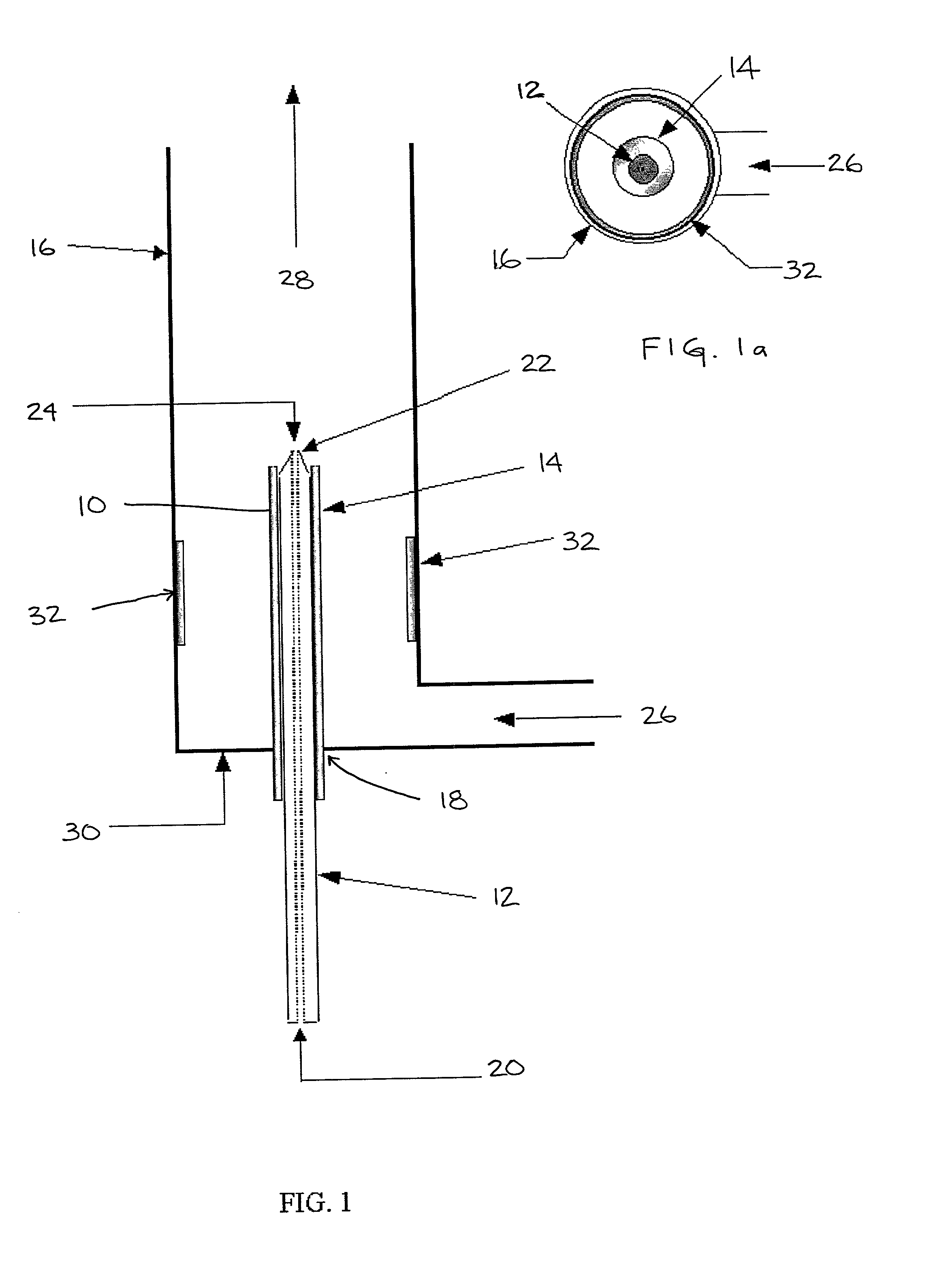
[0027] At least two fluids are introduced into the device. A first fluid that may comprise one or more fluids or
chemical species is conveyed in the outer tube 16. A second fluid that also may comprise one or more fluids or
chemical species is conveyed in the inside of the
metal capillary or
injector tube. In the illustrated embodiment, the first fluid is conveyed in the annular space between nonconductive tube that insulates the capillary and the outer tube and forms the continuous phase of a solution of the first and second fluids. The second fluid, which may be miscible, partially miscible or immiscible with the first fluid forms the dispersed phase in the solution. The flow rate of both fluids may be adjusted individually to affect the output flow. For example, the ratio of the flow of either fluid may be adjusted relative to the other fluid to affect the
reaction dynamics. Application of a high-
voltage potential difference between the
metal capillary and the outer
electrode or conductive portion results in enhanced mixing of the two fluids. This mixing is due to electrohydrodynamic flows caused by the motion of charge carriers in the
electric field.
[0036] The method of the present invention provides a process for rapid dispersion, dissolution, and / or liquid-phase reactions. The process is accomplished through the use of electrohydrodynamic flows in the vicinity of an electrified capillary tube placed inside another tube to induce efficient turbulent mixing of two fluids, which may contain reactive species. The process may be accomplished through the use of one or more capillary tubes. Rapid micromixing allows liquid-phase reactions to be conducted at high rates.
[0038] In one method of the present invention, two fluids are introduced into the reactor. The first fluid comprises a reactive species and is introduced through the capillary tube inlet 20 and injected through the capillary tube 12, and a second fluid is introduced through the inlet 26 of the outer tube 16 in the annular space between the capillary tube 12 and the outer tube 16. The second fluid contains a species reactive with that of the first fluid. Electrohydrodynamic flows caused by
charge injection at the tip 22 of the capillary tube 12 induce turbulent mixing in the vicinity of the tip 22. This leads to rapid and
complete mixing of the reactants. The mixed fluids pass down the outer tube 16, during which time the reactions proceed.
[0039] One method of the present invention is described in the U.S.
Patent Application "Method for the Production of Ultrafine Particles by Electrohydrodynamic Micromixing", David W. DePaoli, Constantinos Tsouris, and Zhong-Cheng Hu, filed concurrently herewith and which is incorporated herein by reference in its entirety. In one of the methods described in the above referenced U.S.
Patent Application, fluids containing species that undergo particle-producing reactions are introduced into the reactor. Suitable reaction systems for the present invention include
sol-gel reactions. For example,
sol-gel reactions can be conducted employing a first fluid comprised of organometallic species such as alkoxides dissolved in an
alcohol. Suitable alkoxides include, but are not limited to,
zirconium butoxide,
zirconium ethoxide, or
zirconium isopropoxide. Examples of alcohols include, but are not limited to,
ethanol,
butanol,
methanol, and isopropanol. The reactant in the second fluid is typically water, which induces
hydrolysis and condensation of the alkoxides in the first fluid. This approach allows continuous or
batch production of non-agglomerated, monodispersed, submicron-sized, sphere-like powders. The size and homogeneity of the product can be controlled through selection of
reaction conditions, including reactant concentrations, type of
solvent, fluid flow rates, and applied
voltage.

